Basics communication
EL33xx-00x0
37
Version: 4.2
Example "Set SM watchdog"
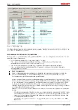
This checkbox enables manual setting of the watchdog times. If the outputs are set and the EtherCAT
communication is interrupted, the SM watchdog is triggered after the set time and the outputs are erased.
This setting can be used for adapting a terminal to a slower EtherCAT master or long cycle times. The
default SM watchdog setting is 100 ms. The setting range is 0..65535. Together with a multiplier with a range
of 1..65535 this covers a watchdog period between 0..~170 seconds.
Calculation
Multiplier = 2498 → watchdog base time = 1 / 25 MHz * (2498 + 2) = 0.0001 seconds = 100 µs
SM watchdog = 10000 → 10000 * 100 µs = 1 second watchdog monitoring time
CAUTION
Undefined state possible!
The function for switching off of the SM watchdog via SM watchdog = 0 is only implemented in terminals
from version -0016. In previous versions this operating mode should not be used.
CAUTION
Damage of devices and undefined state possible!
If the SM watchdog is activated and a value of 0 is entered the watchdog switches off completely. This is
the deactivation of the watchdog! Set outputs are NOT set in a safe state, if the communication is inter-
rupted.
3.4
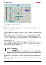
EtherCAT State Machine
The state of the EtherCAT slave is controlled via the EtherCAT State Machine (ESM). Depending upon the
state, different functions are accessible or executable in the EtherCAT slave. Specific commands must be
sent by the EtherCAT master to the device in each state, particularly during the bootup of the slave.
A distinction is made between the following states:
• Init
• Pre-Operational
• Safe-Operational and
• Operational
• Boot
The regular state of each EtherCAT slave after bootup is the OP state.
Summary of Contents for EL33-00 Series
Page 2: ......
Page 6: ...Table of contents EL33xx 00x0 6 Version 4 2...
Page 17: ...Product overview EL33xx 00x0 17 Version 4 2 Fig 10 EL3312 Fig 11 EL3314...
Page 18: ...Product overview EL33xx 00x0 18 Version 4 2 Fig 12 EL3314 0002 Fig 13 EL3314 0010...
Page 61: ...Mounting and wiring EL33xx 00x0 61 Version 4 2 Fig 45 EL3314 0010 Fig 46 EL3314 0090...

