background image

Product overview

CP69xx

14

Version: 3.0

3.3

Status LEDs

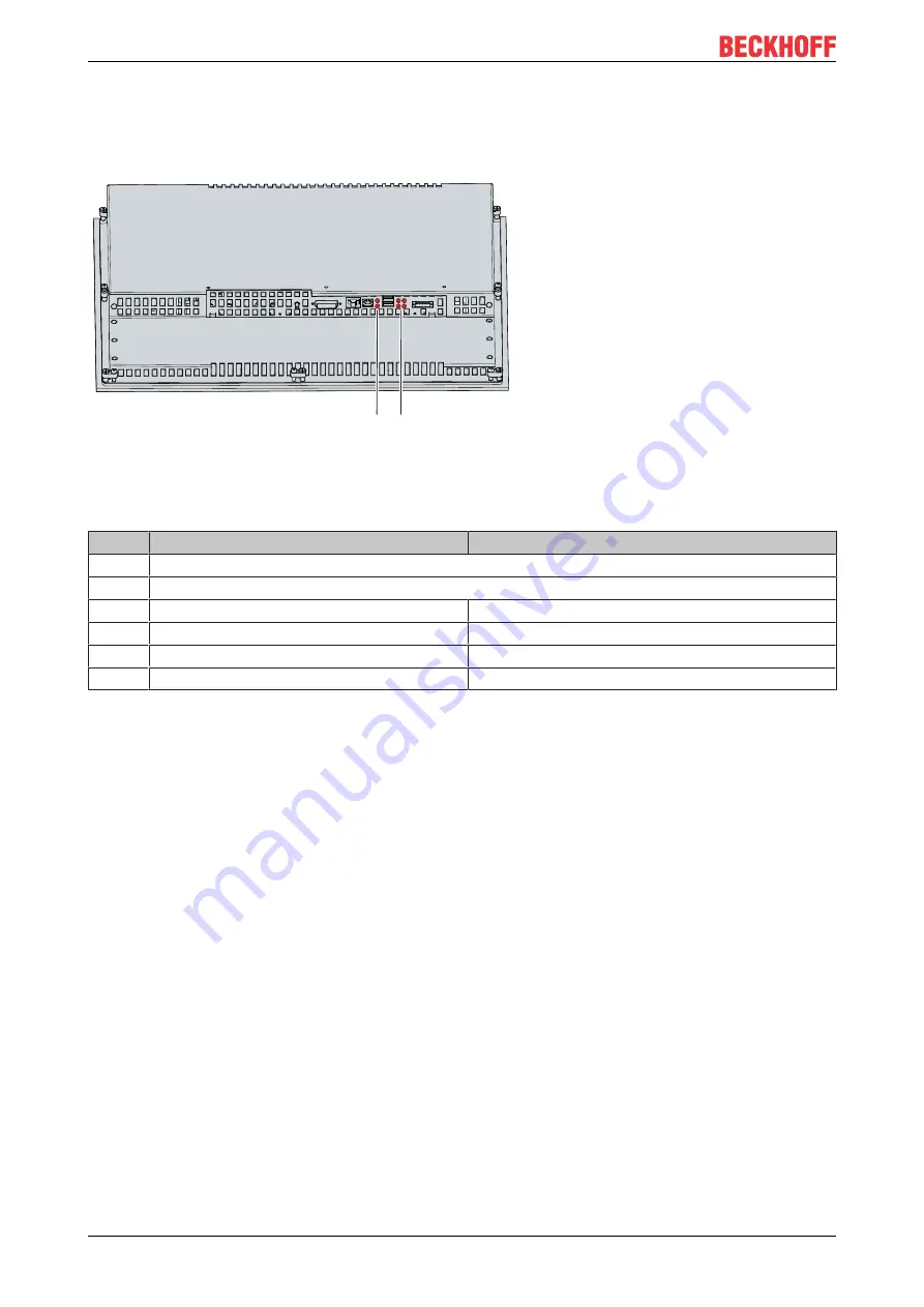
The Control Panel has six status LEDs. They are located on the rear side in the connection section of the
panel (see fig. 8).

Fig. 8: CP69xx_Status LEDs

The LEDs have the following meanings:

Table 7: LED functions

LED

Name

Meaning

1

No function

2

No function

3

USB 1

USB 1 interface in operation

4

USB 2

USB 2 interface in operation

5

Power Good

Input voltage OK

6

24 V in

Power supply established

Summary of Contents for CP69 Series

Page 1: ...Manual EN CP69xx Control Panel 2022 8 2 Version 3 0...

Page 2: ......

Page 3: ...t 12 3 2 3 USB input 12 3 2 4 USB output 13 3 2 5 Power supply 13 3 3 Status LEDs 14 3 4 Name plate 15 3 5 Key functions 16 3 6 Connection kits 18 4 Commissioning 19 4 1 Transport and unpacking 20 4 2...

Page 4: ...Table of contents CP69xx 4 Version 3 0...

Page 5: ...erCAT EtherCAT G EtherCAT G10 EtherCAT P Safety over EtherCAT TwinSAFE XFC XTS and XPlanar are registered and licensed trademarks of Beckhoff Automation GmbH Other designations used in this publicatio...

Page 6: ...erty 2 2 Intended use The CP69xx Economy built in Control Panel is designed for industrial applications in machine and system engineering A TFT display and a single finger touch screen or touch pad an...

Page 7: ...and automation engineering background operate the device Use by unauthorized persons can lead to damage to property and loss of data Fuse the power supply line to protect the supply line in the event...

Page 8: ...rks The latter should be connected to the corporate network or the Internet only if appropriate protective measures have been set up In addition the recommendations from Beckhoff regarding appropriate...

Page 9: ...640 x 480 6 5 inch 640 x 480 12 inch 800 x 600 15 inch 1024 x 768 19 inch 1280 x 1024 TFT display Sheet steel housing with aluminum front front IP65 rear IP20 Front laminate in different variants only...

Page 10: ...rol cabinet 3 Grounding bolt Functional earth of the Control Panel 4 Access to interfaces Interfaces on the underside 3 2 Interface description In the basic configuration the Control Panel includes th...

Page 11: ...Data 4 12 TDMS Data 3 20 TDMS Data 5 5 TDMS Data 4 13 TDMS Data 3 21 TDMS Data 5 6 DDC Clock 14 5V Power 22 TDMS Clock Shield 7 DDC Data 15 Ground 5 V Analog H V Sync 23 TDMS Clock 8 Analog Vertical S...

Page 12: ...ck to USB This is not an Ethernet connection No Ethernet switch or hub can be integrated in the USB Extended cable 8 1 X10² Fig 4 CP69xx_USB E input pin numbering Table 3 USB E input pin assignment Pi...

Page 13: ...socket pin numbering Table 6 Voltage socket pin assignment Pin Signal Description 1 NC not used 2 NC not used 3 Protective earth 4 24 V power supply negative pole 5 24 V 24 V power supply positive po...

Page 14: ...side in the connection section of the panel see fig 8 Fig 8 CP69xx_Status LEDs The LEDs have the following meanings Table 7 LED functions LED Name Meaning 1 No function 2 No function 3 USB 1 USB 1 int...

Page 15: ...supply 24 VDC NEC class 2 8 Grounding bolt for functional earthing of the Control Panel 9 DVI Extended interface X101 10 USB Extended Interface X102 11 USB input X103 12 Status LEDs P101 and P102 wit...

Page 16: ...page Pg Dn turn back one page Tabulator cursor to next input field Shift Tab cursor to previous input field Del Del delete character to the right of the cursor Ins Ins overwrite character to the right...

Page 17: ...r to the cursor position F1 F2 F3 F4 F5 F6 F7 F8 F5 F6 F7 F8 F9 F10 F11 F12 Function keys F1 F10 functions of the keys determined by the software and displayed in the lower display edge Einschub Strei...

Page 18: ...converter to the PC C9900 K627 30 m connection kit for CP29xx 0000 CPX29xx 0000 and CP69xx xxxx 0010 consisting of 30 m DVI cable 30 m Cat 5 cable for USB E 2 0 CU8801 USB to USB E 2 0 converter for...

Page 19: ...ere to the glove If you as the user require additional protection for the touch screen against dirt and scratching for example due to dirty hands this can be achieved with a Beckhoff protective film T...

Page 20: ...o the device Protect the device against moisture condensation during transport in cold weather or in case of ex treme temperature fluctuations Do not put the device into operation until it has slowly...

Page 21: ...e required installation cutout according to the device dimensions of the Control Panel The wall thickness must be between 2 mm and 5 mm for installation After installation be sure to check the tightne...

Page 22: ...e steps shown in Fig 11 and 12 1 Insert the Control Panel at the intended position in the panel of the control cabinet Make sure that the device is secured against falling out until it is fastened pro...

Page 23: ...Commissioning CP69xx 23 Version 3 0 A B C Fig 12 CP69xx_control cabinet installation...

Page 24: ...power supply of the Control Panel using the material supplied for connector assembly It consists of a 5 pin connection strip and a strain relief housing with cable tie If you require a replacement for...

Page 25: ...move the strain relief housing proceed as follows 1 Use your fingers to bend the latching lugs on the lower part slightly outwards see Fig 14 2 Lever the upper part off the lower part 3 Cut the cable...

Page 26: ...ng the Control Panel without functional earth can lead to hardware damage due to electromagnetic inter ference Only use the device with functional earth Electromagnetic compatibility EMC of the Contro...

Page 27: ...data transmission cables When connecting the Control Panel to an Industrial PC with UPS output Beckhoff recommends using this for the connection Connect power cable Cables with a maximum cable cross...

Page 28: ...l during a thunderstorm Before removing the Control Panel you must follow the steps below 1 Shut down the Control Panel 2 Disconnect the Control Panel from the power supply see below 3 Disconnect the...

Page 29: ...shown in Fig 16 and 17 1 Loosen the clamping levers with a 3 0 mm Allen key sections A and B 2 Fold the clamping levers back by 90 onto the housing section C C B A Fig 16 CP69xx_removal from the contr...

Page 30: ...ning agents Examples include benzine spirit acetone Glass cleaner Avoid the following cleaning agents Detergents with scouring or abrasive components Metal cleaning objects such as razor blades or ste...

Page 31: ...n Cleaning mode The period can be set between 5 and 120 seconds Right click the sun symbol again and click Options Now select the appropriate period see fig 19 Fig 19 CP69xx_Options Repair Only the ma...

Page 32: ...r missing functional earth of the device Poor or missing ground connection of the user Check potential equalization and grounding measures Touch the Control Panel frame and check the touch function at...

Page 33: ...y conforms to EN 61000 6 2 EMC interference emission conforms to EN 61000 6 4 Permissible ambient temperature Operation 0 C to 55 C Transport storage 25 C to 65 C Permissible relative air humidity Max...

Page 34: ...an be found on the name plate Beckhoff Support Support offers you comprehensive technical assistance helping you not only with the application of individual Beckhoff products but also with other wide...

Page 35: ...against adverse interference if the device is used in a commercial environment This device generates uses and may emit radio frequency energy and may cause adverse interference with radio communicati...

Page 36: ...numbering 13 Fig 8 CP69xx_Status LEDs 14 Fig 9 CP69xx_name plate 15 Fig 10 CP69xx_delivery state clamping lever 22 Fig 11 CP69xx_wall positioning 22 Fig 12 CP69xx_control cabinet installation 23 Fig...

Page 37: ...le 3 USB E input pin assignment 12 Table 4 USB interface pin assignment 12 Table 5 USB interface pin assignment 13 Table 6 Voltage socket pin assignment 13 Table 7 LED functions 14 Table 8 Key CP69xx...

Page 38: ......

Page 39: ...Beckhoff Automation GmbH Co KG H lshorstweg 20 33415 Verl Germany Phone 49 5246 9630 info beckhoff com www beckhoff com More Information www beckhoff com cp69xx...

Reviews: