First Steps
BK7150
21
Version: 1.0.0
4
First Steps
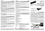
Address-Switch
S3 for Baudrate
0 – 156 kBaud
1 – 625 kBaud
2 – 2,5 MBaud
3 – 5 MBaud
4 – 10 MBaud
5 – 9 no function (reserve)
S1 address x 1
S2 address x 10
Example:
S3 = 2
S1 = 4
S2 = 1
Baudrate = 2,5 MBaud, address = 14
Addressing I/Os from the K-Bus interface:
The coupler has an automatic mapping. The coupler reads the terminals and configures the CC-Link
interface. The coupler has four different CC-Link mappings.
16 DI/16 DO and/or 4 channel in/out (8 Byte in/out)
48 DI/48 DO and/or 8 channel in/out (16 Byte in/out)
80 DI/80 DO and/or 12 channel in/out (24 Byte in/out)
112 DI/112 DO and/or 16 channel in/out (32 Byte in/out)
On start up, the BK7150 reads the terminals and configures the CC-link interface. The I/O error LED the
coupler shows which mapping is active.
I/O Error LED is flashing once, the mapping 1 is active.
I/O Error LED is flashing twice, the mapping 2 is active.
I/O Error LED is flashing three times, the mapping 3 is active.
I/O Error LED is flashing fore times, the mapping 4 is active.
Mapping digital I/Os:
RX/RY
Number of occupied stations
Mapping
1
2
3
4
00-0F
DI/DO
DI/DO
DI/DO
DI/DO
01-1F
Status/Control
DI/DO
DI/DO
DI/DO
02-2F
-
DI/DO
DI/DO
DI/DO
03-3F
-
Status/Control
DI/DO
DI/DO
04-4F
-
-
DI/DO
DI/DO
05-5F
-
-
Status/Control
DI/DO
06-6F
-
-
-
DI/DO
07-7F
-
-
-
Status/Control
Sum
16 DI/16 DO
48 DI/48 DO
80 DI/80 DO
112 DI/122 DO
Status RX
xxB
Station Ready
xxA
K-Bus Error
Control RY
xxA
Reset K-Bus


