Mounting and wiring
BC5250
25
Version: 2.0.0
3.2.4.9
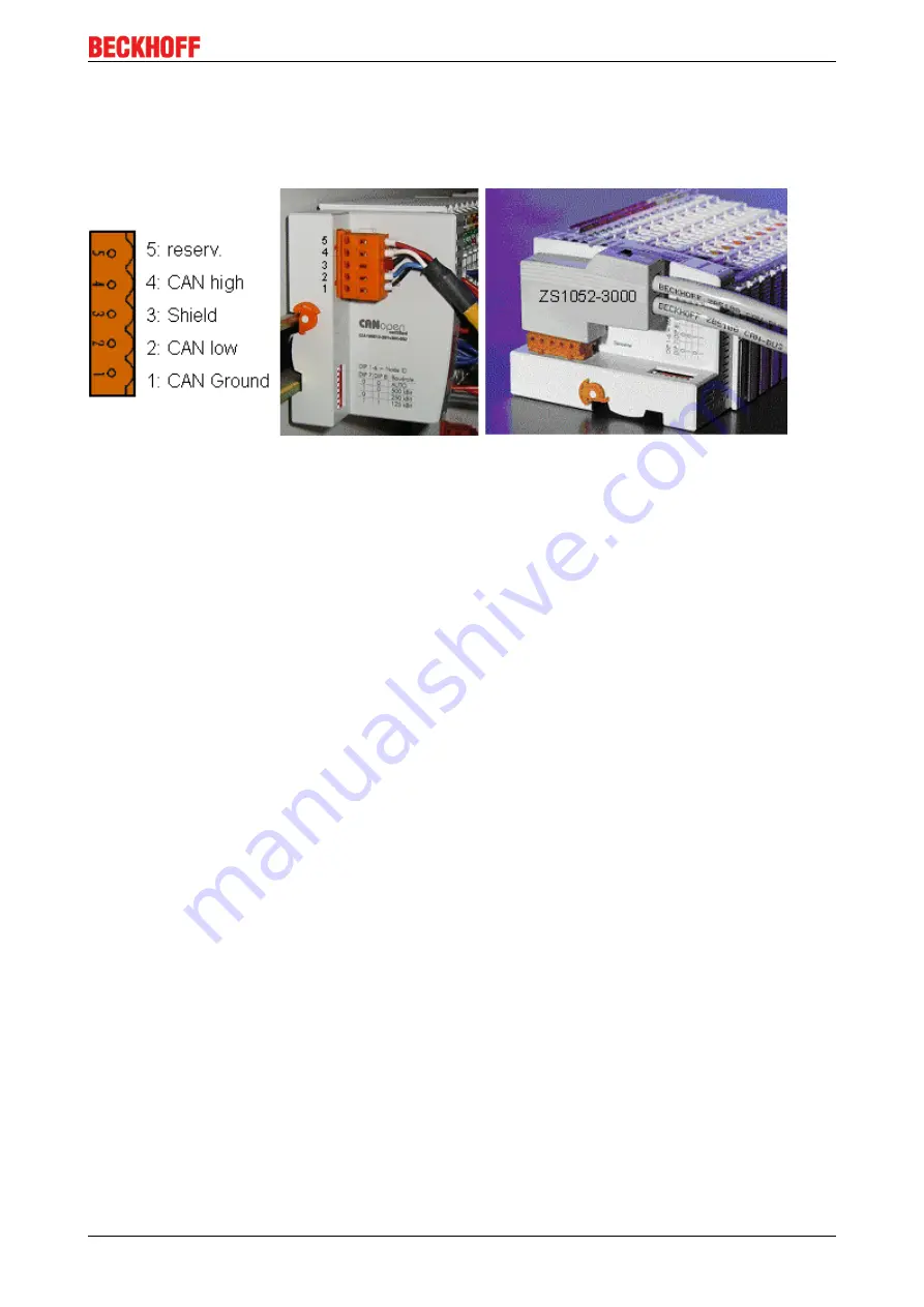
BK52x0/BX5200: 5-pin open style connector
The BK52x0/BX5200 (X520) Bus Couplers have a recessed front surface on the left hand side with a five pin
connector.
The supplied DeviceNet connecting socket can be inserted here.
Fig. 15: BK51x0/BX5100 connection socket assignment
The left figure shows the socket in the BK52x0/BX5200 Bus Coupler. Pin 5 is the connection strip's top most
pin. Pin 5 is not used. Pin 4 is the CAN high connection, pin 2 is the CAN low connection, and the shield is
connected to pin 3 (which is connected to the mounting rail via an R/C network). CAN-GND can optionally be
connected to pin 1. If all the CAN ground pins are connected, this provides a common reference potential for
the CAN transceivers in the network. It is recommended that the CAN GND be connected to earth at one
location, so that the common CAN reference potential is close to the supply potential. Since the CANopen
BK52x0/BX5200 Bus Couplers provide full electrical isolation of the bus connection, it may in appropriate
cases be possible to omit wiring up the CAN ground.
3.2.4.10
ZS1052-3000 Bus Interface Connector
The ZS1052-3000 CAN Interface Connector can be used as an alternative to the supplied connector. This
makes the wiring significantly easier. There are separate terminals for incoming and outgoing lines and a
large area of the shield is connected via the strain relief. The integrated termination resistor can be switched
externally. When it is switched on, the outgoing bus line is electrically isolated - this allows rapid wiring fault
location and guarantees that no more than two resistances are active in the network.
3.2.4.11
Fieldbus Box: M 12 DeviceNet socket
Fieldbus Box: M12 DeviceNet socket
With the IPxxxx-B520 and IL230x-B520 Fieldbus Box modules, a five-pole M12 connector is used for the bus
connection.


