BE Ag & Industrial 35.001.500 Operating Instructions Manual Download Page 3


USER MANUAL     

3

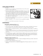
ASSEMBLY INSTRUCTIONS

IMPORTANT:

Upon raising vehicle, the jack must IMMEDIATELY be locked into one of the three lift heights.
• Precision controlled foot release Pedal (19) (Fig. 1) for lowering the vehicle.
• Can be used as a dolly to move your vehicle to a convenient location for working or storage.
• T-Handle (Fig. 1) for added control when dollying vehicle into working or storage location.
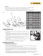
(see Fig. 1)

1.  Attach Hydraulic Ram (20) to the Ram Platform (24) with Bolts (21) and 

Washers (22).

2.  Remove Cotter Pin and Lock Pin (17) from Ram. Raise Load Frame (23) by 

hand and align the Head of the Hydraulic Ram (20) with the Tab Holes in 

the Low Centre of the Load Frame. Replace Lock Pin (17) and secure with 

Cotter Pin(12).

3.  To install Lock Bar, align High Lock Release (11) into Height Lock Bar (2) on 

both sides and secure using Washers (10) and Nuts (9).

4.  Insert Foot Pedal Arm (18) into the sleeve of Hydraulic Ram (20) and secure 

with Bolt (16).

5.  Attach T Handle (13) to Connecting Rod (25) with Handle Pin (14).
6.  Make sure that all connections are tightened thoroughly.

REF

PART  NUM

DESCRIPTION

QTY

1

105.101B.001

Caster assembly

 2

2

Height lock bar

2

3

Stops

2

4

105.101B.002

Front wheels

2

5

Frame

1

6

Front load frame

1

7

Lift saddle

2

8

105.101B.003

Rubber pads

2

9

M8 nut

2

10

Ø 8 Lock washer

2

11

High lock release

1

12

Cotter pin

1

13

105.101B.004

T handle

1

14

Handle pin

1

15

Safety set screw

1

16

Bolt (M8 x 12)

1

17

Lock pin

1

18

105.101B.005

Foot pedal

1

19

105.101B.006

Release pedal

1

20

105.101B.007

Hydraulic ram

1

21

Bolt (M8 x 25)

2

22

Washer

2

23

Load frame

1

24

M8 nut

2

25

Connecting rod

1

Fig. 1

Pedal

Fig. 2

OPERATING INSTRUCTIONS

TO RAISE THE VEHICLE (SEE FIG. 1, 2)

1.  Place jack on a hard level surface.
2.  To avoid item from slipping during the raising operation, ONLY lift on points of vehicle specified by 

vehicle manufacturer in the vehicle‘s operator‘s manual.

3.  Place the jack under the vehicle so that the Lift Saddle is positioned under the vehicle‘s lift point.
4.  Pump the foot pedal (18) (see Fig. 1) until the lift saddle (7) comes in contact with the vehicle to be 

lifted; ALWAYS check to be sure that the saddle and the vehicle are positioned correctly BEFORE 

raising the jack.

5.  Use Foot Pedal to raise vehicle. Pump Foot Pedal until tip of Height Lock Bar moves past desired lock 

position ridge. The tip of the Height Lock Bar will sink into position just behind the ridge. Depress 

release pedal slightly so that the tip moves snugly against ridge.

Summary of Contents for 35.001.500

Page 1: ...3 4 6 14 5 9 9 This is the safety notification symbol This symbol will notify you of any potential injury hazards Please follow all instructions that follow this symbol to avoid possible injuries or...

Page 2: ...aged parts are noted Immediately after raising the vehicle ensure that the Height Lock Bar is engaged ALWAYS wear safety glasses when operating this product NEVER place yourself under or in a position...

Page 3: ...r 2 3 Stops 2 4 105 101B 002 Front wheels 2 5 Frame 1 6 Front load frame 1 7 Lift saddle 2 8 105 101B 003 Rubber pads 2 9 M8 nut 2 10 8 Lock washer 2 11 High lock release 1 12 Cotter pin 1 13 105 101B...

Page 4: ...After all of the old oil has drained out of the jack turn the jack back over to a level position to fill with new oil Rapidly pump foot pedal 18 6 to 8 full strokes to release any pressurized air Usin...

Page 5: ...e not responsible for damage to ornamental designs you place on this BE AG INDUSTRIAL product and such ornamentation should not cover any warnings or instructions or they may void the warranty This wa...

Page 6: ...nstructions qui accompagnent ce symbole pour viter tout risque de blessure ou de mort Indique une situation de danger Le non respect des mesures appropri es peut entra ner la mort ou des blessures gra...

Page 7: ...r de le dolly ou de le d placer N apportez AUCUNE modification ce produit Inspectez TOUJOURS le cric avant chaque utilisation NE PAS utiliser si une fuite de liquide et ou des pi ces cass es pli es fi...

Page 8: ...llage commande de pr cision 19 Fig 1 pour abaisser le v hicule Peut tre utilis comme chariot pour d placer votre v hicule vers un emplacement pratique pour le travail ou le stockage Poign e en T Fig 1...

Page 9: ...que l article ne glisse pendant l op ration de levage soulevez UNIQUEMENT les points du v hicule sp cifi s par le constructeur du v hicule dans le manuel d utilisation du v hicule 3 Placez le cric sou...

Page 10: ...tout air sous pression l aide d une huile de v rin hydraulique SAE 5W de bonne qualit remplissez le r servoir jusqu au bas des filets de l orifice de remplissage d huile NE LAISSEZ PAS la salet et le...

Page 11: ...nul e Nous ne sommes pas responsables des dommages caus s aux motifs ornementaux que vous placez sur ce produit BE AG INDUSTRIAL et ces ornements ne doivent pas couvrir les avertissements ou les instr...

Page 12: ...12 USER MANUAL PARTS BRABEREQ COM TOLL FREE PHONE NUM RO DE T L PHONE SANS FRAIS 1 877 588 3311...

Reviews: