Bazell Microseparator Transport, Installation And Initial Startup Download Page 19

 Microseparator™ Coolant Systems                                                        Transport, Installation, & Initial Startup 

M000005_A - V Twin Ultra Transport & Installation 5.2-EN TM                                                                                       

19/78


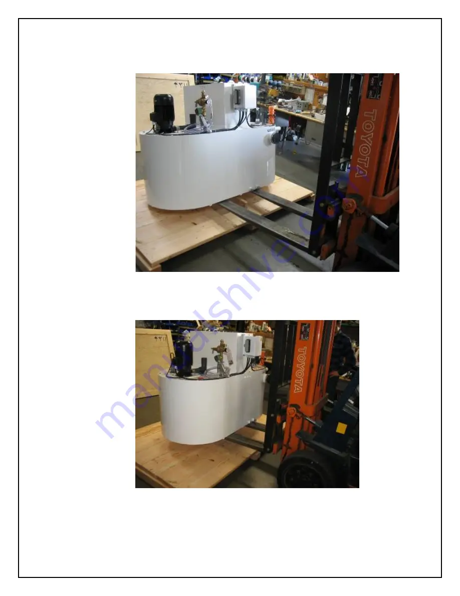
Lifting the Main Tank Assembly 


Figure 8 - Lifting Main Tank Assy 

After removing the surrounding crating material and packaging, lift the 

tank assembly as shown.  Block with wood to allow the forklift tangs to 

pass fully under the tank assembly. 


Figure 9 - Lifting Main Tank Assy 

Lift the entire assembly and transport to the installation point. 

Summary of Contents for Microseparator

Page 1: ...y Bazell Technologies Corporation 5066 Commercial Circle Concord CA 94520 Tel 925 603 0900 Fax 925 603 0901 Email info bazell com Web www bazell com Sold exclusively by SatisLoh Confidential to Satisl...

Page 2: ...ions 12 8 Delivery 12 8 1 General 12 8 2 Dimensions of the Machines 13 9 Transport 14 9 1 Overview 14 9 2 General Instructions for Transport 14 9 3 Transport by Crane 14 9 4 Transport with a Fork Lift...

Page 3: ...2 Microseparator Coolant System HC 28 11 3 Chip Separator with Tank Short 6SIGD001 29 11 3 1 Chip Separator with Tank Setup Options 30 11 4 Chip Separator with Tank Tall Drawing 6SATD001 31 11 5 Pump...

Page 4: ...on of Connections 53 18 6 Electrical Power 54 18 6 1 Connection Point at the Machine 54 18 7 Compressed Air 54 18 7 1 Connection Point at the Machine 54 18 8 Coolant Supply to the Machine 54 18 8 1 Co...

Page 5: ...2 Floor Requirements 59 19 4 3 Electromagnetic Influence 60 19 5 Dimensions of the Machine 60 19 6 Connecting the Chip Separator with Tank Tall 61 19 6 1 Connection Safety Instructions 61 19 6 2 Descr...

Page 6: ...67 20 10 Coolant Pipeline Connections 67 20 10 1 Dirty Coolant Drain from the Generator 67 20 11 Retrieval of Deblocked Lenses 67 21 Chip Separator Assemblies Without Pumping Tank 68 21 1 Principles...

Page 7: ...21 8 1 Connection Point at the Machines 73 21 9 Coolant Pipeline Connections 73 21 9 1 Dirty Coolant Drain from the Chip Separators 73 22 Microseparator Daily Operation 74 22 1 Preliminary Checks 74 2...

Page 8: ...ps Prepare for the installation of the equipment Transport the machinery safely Install the machine safely and easily Connect the machines correctly Perform an initial startup Always keep this manual...

Page 9: ...arately from this document If you require additional copies please contact Bazell Technologies by telephone at 800 288 2465 or 925 603 0900 or by email info bazell com Please provide the system serial...

Page 10: ...ruction and supervision of a qualified electrician may do any work on electrical equipment and systems 2 Always disconnect and lock out the power source before working on or near the Microseparator ro...

Page 11: ...coolant flow 45 GPM 170 lpm Centrifuge capacity 2 1 gal 7 9 litres cycle All Chip Separators With Pump Tank Maximum connected generators 1 ea Maximum coolant flow 25 GPM 95 lpm Chip Separators Withou...

Page 12: ...Chip Separator with Transfer Tank is required per generator Separation of milling and turning debris remotely near the main coolant tank This method requires use of the Pump Station to move all lens...

Page 13: ...1829 650 Coolant Tank On Pallet 1219 1219 1930 390 In Crate 1219 1320 1930 434 Control Panel On Pallet 1219 609 2260 210 In Crate 1219 813 2260 244 Chip Separators With Tank Short On Pallet 1067 864 1...

Page 14: ...Over Use caution Attach safety straps to the upper eyebolts on the centrifuge and secure on the forklift mast before lifting 9 3 Transport by Crane If unavoidable the machine can also be transported...

Page 15: ...ke suitable measures to prevent the machines from slipping on the forks e g place the machines on rubber mats The screws with which the machine is fastened to the pallet must not be loosened during tr...

Page 16: ...Figure 2 Lifting CF65G Position forks beneath the pallet for transport to the installation site Remove nuts and washers securing the centrifuge to the pallet and lift the centrifuge by placing the ta...

Page 17: ...the installation site or to the point where it will be mounted to the support stand Figure 5 Lifting CF105 G Alternatively place forks inside the pockets of the transport frame as shown at the red ar...

Page 18: ...suitable lifting straps attached as shown in the photo above lift the centrifuge from the shipping frame after removal of the bolts and washers Align the vibration isolating bolts to the mounting sta...

Page 19: ...fting the Main Tank Assembly Figure 8 Lifting Main Tank Assy After removing the surrounding crating material and packaging lift the tank assembly as shown Block with wood to allow the forklift tangs t...

Page 20: ...that the fork tangs pass fully beneath the assembly as shown in the photo below Lift only from the side of the assembly Damage can result to the interior section of the Pump Station if forklift tangs...

Page 21: ...contact Bazell Technologies in advance of order 10 4 3 Electromagnetic Influence Interference from other electric installations high frequency must be avoided The main system electrical control panel...

Page 22: ...ntenance and service access Observe all state local NEC and NFPA regulations concerning space in front of all opening electrical enclosures Space must be allowed for sliding the sludge box from beneat...

Page 23: ...connection is shown at left Position the pipe supplied as shown and insure flexible connections are securely fastened Two one inch flexible hoses are supplied as shown at left Hose A connects to the c...

Page 24: ...requirements Figure 13 Connecting Power to Main Panel Figure 14 Attach Multi Pin to Main Tank Wiring to the main tank assembly is made through a prewired multi pin connector as shown above Cabling is...

Page 25: ...EN TM 25 78 10 7 Compressed Air Connection Refer to Connection Schedule Drawings for all utility requirements and connection dimensions 10 7 1 Microseparator Standard System CF65 Figure 15 Connect Air...

Page 26: ...Installation 5 2 EN TM 26 78 10 7 2 Microseparator HC System CF105 Refer to Connection Schedule Drawings for all utility requirements and connection dimensions Figure 17 Connect Air Supply to CF105G F...

Page 27: ...lant Systems Transport Installation Initial Startup M000005_A V Twin Ultra Transport Installation 5 2 EN TM 27 78 11 System General Arrangement Drawings Utility Requirements 11 1 Microseparator Coolan...

Page 28: ...Transport Installation Initial Startup M000005_A V Twin Ultra Transport Installation 5 2 EN TM 28 78 Figure 19 Connection Schedule Microseparator 11 2 Microseparator Coolant System HC Figure 20 Connec...

Page 29: ...olant Systems Transport Installation Initial Startup M000005_A V Twin Ultra Transport Installation 5 2 EN TM 29 78 11 3 Chip Separator with Tank Short 6SIGD001 Figure 21 Connection Schedule Chip Separ...

Page 30: ...ated 180 with respect to the tank base In order to rotate the chip separator however the base plate holding the pump and level switches must also be rotated 180 While both objects can be moved 180 the...

Page 31: ...lant Systems Transport Installation Initial Startup M000005_A V Twin Ultra Transport Installation 5 2 EN TM 31 78 Chip Separator with Tank Tall Drawing 6SATD001 Figure 23 Connection Schedule Chip Sepa...

Page 32: ...separator Coolant Systems Transport Installation Initial Startup M000005_A V Twin Ultra Transport Installation 5 2 EN TM 32 78 11 5 Pump Station Drawing 6SATU001 Figure 24 Connection Schedule Pump Sta...

Page 33: ...tor Coolant Systems Transport Installation Initial Startup M000005_A V Twin Ultra Transport Installation 5 2 EN TM 33 78 11 6 Pump Station Drawing 6SATF001 Figure 25 Connection Schedule Pump Station L...

Page 34: ...lant Systems Transport Installation Initial Startup M000005_A V Twin Ultra Transport Installation 5 2 EN TM 34 78 11 7 Chip Separator Single Assembly Drawing 6SATT001 Figure 26 Connection Schedule Chi...

Page 35: ...oolant Systems Transport Installation Initial Startup M000005_A V Twin Ultra Transport Installation 5 2 EN TM 35 78 11 8 Chip Separator Dual Assembly Drawing 6SATK001 Figure 27 Connection Schedule Chi...

Page 36: ...lant Systems Transport Installation Initial Startup M000005_A V Twin Ultra Transport Installation 5 2 EN TM 36 78 11 9 Chip Separator Triple Assembly Drawing 6SATV001 Figure 28 Connection Schedule Chi...

Page 37: ...the following 1 Main power breaker is open as well as auxiliary circuit breakers 2 Close main power breaker in Microseparator control panel and check voltage 3 Close breaker and check incoming voltage...

Page 38: ...solenoid should actuate The scraper socket and stopper should begin to come down on to the rotor If the scraper socket and stopper do not come onto the rotor during this cleaning cycle immediately dis...

Page 39: ...ntation is supplied inside the electrical control panel along with the panel wiring diagrams 15 Cleaning Frequency Calculation The Microseparator centrifuge separates the smallest particles of lens de...

Page 40: ...can be used where necessary 16 Coolant Makeup System Connect the fresh water supply to the inlet of the electric solenoid valve The valve has a 1 2 NPT female thread Place end of clear hose in coolant...

Page 41: ...water thin viscosity 1 0 cp No tip 4 5 1 Gray 690043 128 30 5 1 Black 690042 098 40 6 1 Beige 690041 070 50 9 1 Red 690040 052 55 20 1 White 690049 043 57 24 1 Blue 690039 040 60 26 1 Tan 690038 035 6...

Page 42: ...Checking Flow Rate Microseparator Flow rates are indicated on the control panel Normal flows should lie within the green band The measurement is based upon amp load from the centrifuge drive motor Thi...

Page 43: ...standard Microseparator System with CF65 120 lenses for the Microseparator HC version with CF105 Use these values as a starting point Depending upon the quality of the cutting bits lens material and o...

Page 44: ...the Pump Station is the ability of operators to recover deblocked lenses easily where they occur by simply opening the front access door to retrieve the item Operation of the pump is temporarily inte...

Page 45: ...Hz Power consumption 1 25 KVA Fusing on site 10 A Compressed Air Minimum 4 1 bar 60 PSIG Maximum 6 8 bar 100 PSIG Setting value 4 8 bar 70 PSIG Compatible fluids Domestic water Pure water is not comp...

Page 46: ...te 10 A Compressed Air Minimum 4 1 bar 60 PSIG Maximum 6 8 bar 100 PSIG Setting value 4 8 bar 70 PSIG Compatible fluids Domestic water Pure water is not compatible Coolants Fully synthetic is recommen...

Page 47: ...ransport Installation 5 2 EN TM 47 78 Machine Components Figure 33 Pump Station Machine Components 1 Main Electrical Panel and Disconnect 2 Operator controls Emergency Stop Stop and Start Reset 3 Alar...

Page 48: ...tation Low Profile Machine Components 1 Main Electrical Panel and Disconnect 2 Main Panel Operator controls Emergency Stop Stop and Start Reset with illuminated buttons 3 Remote Operator Emergency Sto...

Page 49: ...oors The area comprises The area taken up by the machine itself Space to remove the interior service module Space to open the front access door 18 3 2 Floor Requirements The installation area for the...

Page 50: ...f the Machine Pump Station A Set aside area to slide out interior service module for pump removal and to allow unobstructed room to open control enclosure B Consult generator manufacturer for set asid...

Page 51: ...51 78 Pump Station Low Profile A Area to allow unobstructed opening of control panel door B Consult generator manufacturer for set aside area to avoid interference with generator service access doors...

Page 52: ...ntenance doors are open Prevent the machine from being switched on unintentionally by pulling the mains plug 18 4 2 Note about connection dimensions Piping electrical and pneumatic connections are sup...

Page 53: ...hown schematically in the figure below Figure 38 Pump Station Connections 1 Clean coolant supply to generator either side one generator only 2 Dirty coolant entrance from generator either side one gen...

Page 54: ...at item 4 Figure 38 Pump Station Connections on page 53 Alternatively the fitting can be removed and a threaded connection with customer supplied fitting can be used 18 8 Coolant Supply to the Machine...

Page 55: ...as shown at item 2 Figure 38 Pump Station Connections on page 53 Only one generator may be connected to each Pump Station 18 11 Dirty Coolant Return to Coolant System Return line connection is a 2 PV...

Page 56: ...the drain fitting specified by the generator manufacturer An open hole is provided to fit the DN100 4 drain pipe into the Machine front section A rubber gasket is supplied fitted to the open hole Remo...

Page 57: ...hine for further detail Make the following checks Test the local rotary field Your machine is designed for a right rotating field It may be necessary to observe impeller rotation using a mirror and fl...

Page 58: ...ided with the equipment typically the limitation is piping overhead at a maximum of 15 4 5m of elevation and a maximum lateral downwardly sloping piping run of 50 15 25m The Chip Separator was develop...

Page 59: ...or 5 Tank assembly with transfer pump and level switches 19 4 Installation Requirements 19 4 1 Work Space Requirements Refer to 19 5 Dimensions of the Machine on page 60 The area comprises The area ta...

Page 60: ...at page 31 for dimension detail The assembly can be positioned with the chip discharge end facing the front or rear of the generator The control panel position is fixed on the assembly Note the follo...

Page 61: ...the machine from being swithchedon unintentionally by pulling the mains plug 19 6 2 Description of Connections Figure 42 Chip Separator with Tank Tall Connections Refer to 11 4 Chip Separator with Ta...

Page 62: ...sponsible to supply compressed air pipeline or hose to the connection point 19 9 Coolant Pipeline Connections Coolant pipelines are specified in the installation specific Piping Installation Drawings...

Page 63: ...vided with the equipment typically the limitation is piping overhead at a maximum of 15 4 5m of elevation and a maximum lateral downwardly sloping piping run of 50 15 25m The Chip Separator was develo...

Page 64: ...l panel with disconnect and operators 2 Pneumatic assembly 3 Lens retrieval access door 4 Alarm 4 5 Vertical centrifugal transfer pump 6 Isolation valve 7 Level switches 20 4 Installation Requirements...

Page 65: ...e reversed relative to the transfer tank see 11 3 1 Chip Separator with Tank Setup Options on page 30 This is only possible on this version of the machine Note the following A Consult generator manufa...

Page 66: ...revent the machine from being switched on unintentionally by pulling the mains plug 20 7 Description of Connections Figure 45 Chip Separator with Tank Short Connections Refer to 11 3 Chip Separator wi...

Page 67: ...ne or hose to the connection point 20 10 Coolant Pipeline Connections Coolant pipelines are specified in the installation specific Piping Installation Drawings supplied with the machine For all models...

Page 68: ...discharge pipeline of one Pump Station mineral glass is not recommended The distance from the Chip Separator to the remote Pump Station is limited by the specifications contained in the Piping Instal...

Page 69: ...n Ultra Transport Installation 5 2 EN TM 69 78 21 3 Machine Components Figure 46 Dual Chip Separator Assembly Components 1 Electrical junction box power from Microseparator system 2 Pneumatic assembly...

Page 70: ...Assembly Drawing 6SATV001 page 36 And 21 4 4 Dimensions of the Machine s on page 71 The area comprises The area taken up by the machine itself Space to remove the debris bin s Space to open the juncti...

Page 71: ...cess areas A The height of the assembly is fixed by the dimension of the supporting structure However since fluid is pumped into the Chip Separators from overhead and fluid gravity drains into the Mic...

Page 72: ...ions Refer to the following drawings contained in this document 11 7 Chip Separator Single Assembly Drawing 6SATT001 page 34 11 8 Chip Separator Dual Assembly Drawing 6SATK001 page 35 11 9 Chip Separa...

Page 73: ...Separator Single Assembly Drawing 6SATT001 page 34 11 8 Chip Separator Dual Assembly Drawing 6SATK001 page 35 11 9 Chip Separator Triple Assembly Drawing 6SATV001 page 36 And see 21 6 Description of...

Page 74: ...Check air supply at main air regulator is 4 bar 60 psig 4 Check air purge regulator set to 5 bar 7 psig 5 Empty the swarf cart under the Microseparator centrifuge 6 Confirm coolant concentrate and de...

Page 75: ...he Chip Separator Transfer Tanks Caution Do not use Emergency Stop or turn off main breaker to shut down main system during normal shut down procedure The Microseparator should always go through a cle...

Page 76: ...am agent for low foaming Anti fungal agents prevent fungal and bacterial growth in complete circulation process Free rinsing formulation prevents sticky film build up on lenses as well as machine tool...

Page 77: ...ptions Chip Separator w Tank Short 30 Figure 23 Connection Schedule Chip Separator w Tank Tall 31 Figure 24 Connection Schedule Pump Station 32 Figure 25 Connection Schedule Pump Station Low Profile 3...

Page 78: ...rtup M000005_A V Twin Ultra Transport Installation 5 2 EN TM 78 78 Figure 46 Dual Chip Separator Assembly Components 69 Figure 47 Chip Separator Assembly Dimensions 71 Figure 48 Chip Separator Assembl...

Reviews: