This spacer kit Installation instruction is for use with
Valor spacer kits Part No. 595129 & 595139
.
Section 1
is for all models except those fitted with a CHIC fascia.
Section 2
is for models fitted with the CHIC fascia only.
The above kits shall only be used for installations with Valor models 540 & 541 and must be used in conjunction with the
Installer guides supplied with the appliance.
Section 1
(For all models except those fitted with a CHIC fascia. For models fitted with a CHIC fascia see section 2 on page 2).
Pack contents
1 off spacer frame.
1 off wall template.
4 off self-tapping screws in a bag.
2 off strengthening bars.
Installation
Method 1 (Drilling and screwing)
1. The hearth and the hole for the flue must be in place.
2. Remove the spacer frame from its protective wrapping.
3. The wall template has four fixing hole positions. Pierce the centre of these holes before continuing.
4. Position the centre line of the wall template so that it is in line with the centre line of the hole for the flue / centre line
of opening in the surround. The base of the template indicates the hearth height. The template can be cut along this
line to assist in correct positioning of the template.
5. Mark the positions of the four fixing holes on the wall / surround. Remove the template.
6. Drill the four fixing holes to a minimum depth of 42mm using a 7mm diameter masonry drill.
7. Insert the four wall plugs supplied with the appliance (Not with the spacer frame).
8. Position the spacer frame to the wall / surround. The wider flange and larger holes go against the wall.
9. Secure the spacer frame to the wall or surround using the four wood screws that are supplied with the appliance.
Please note that for Timber frame installations the use of ceramic fibreboard may be required before installing the
appliance (See the appropriate section in the installer guide).
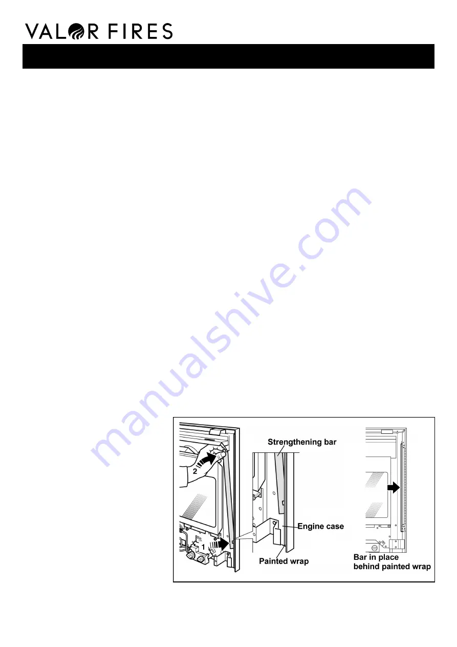
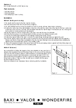
10. Strengthening bars are supplied to prevent distortion when securing the appliance to the spacer frame. There is a
gap at each side between the rear flanges of the painted engine wrap and the unpainted engine case. Slide the
strengthening bars into the gaps as shown in figure 1. The bars should be positioned so that the notch near the
bottom of each bar and the cut-out at the top corner of each bar will allow the fixing screws to pass through. With the
strengthening bars in place, secure the
appliance engine to the spacer frame
with the four tapping screws supplied
with the kit.
11. Continue with the installation as in the
installer guide.
Method 2 (Adhesive)
As an alternative to drilling and plugging it
may be preferable to use some form of
adhesive (Not supplied) to secure the
spacer frame to the surround. This
adhesive may be in the form of silicon
sealant, contact adhesive or double-sided
tape, all of which should be suited to high
temperature environments (At least 100°C).
It is advised that the wall template be used
as a guide for marking the position of the
fixing holes as above. These can then be used as an indicator that the spacer frame is positioned correctly.
Allow any adhesive to dry completely before continuing with the installation.
Figure 1.
© Baxi Heating U.K. Limited 2007.
540 & 541 Spacer kit
600B470-04


