


TAM 00746
25
DSP1 045 - 100
11 / 2019
Three phase synchronous motor
English
8.4 Main and control connection via combination mounting socket
(customer-
specific version)
The combination mounting box is generally mounted on the B end plate of the drive. The box is
angled at 90° and, contrary to the standard design of the motors, cannot be rotated.
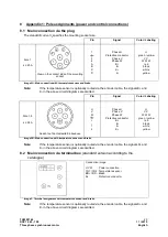
Image 5: Pin assignment of the comination mounting box
Outdoor area:
Pin "B to A" shows the pole assignment for power connection and PE brake.
Indoor area:
Pin "1 to 12" shows the pole assignment for resolver and temperature sensor..
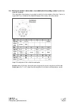
Pin
1
2
3
4
5
6
Signal
Sin 1
Sin 2
/
/
/
Shield
Color
LTN
yellow
blue
Pin
7
8
9
10
11
12
Signal
Ref 1
K+
K-
Ref 1
Cos 1
Cos 2
Color
LTN
black /
white
yel-
low
black
red /
white
red
black
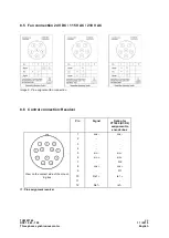
Pin
B
┴
U
V
W
N
A
Signal
Br. -
┴
U
V
W
Br. +
Color
black
red


