Installation
Instruction handbook
b maXX
BM5500, BM5600, BM5700
Document No.: 5.13008.10
179
7
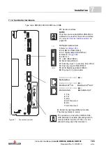
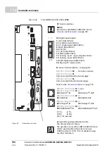
7.11.2 Terminal overviews
on page 183 and the following show the connections for protective conduc-
tors, power supply, motor, brake resistor, DC-link and motor temperature sensor (X101).
from page 193 shows the control voltage and the connections
of the controller unit.
NOTE!
The use of the ballast switch is not possible in combination with a disabled safety re-
lay of a BM551X or BM552X.
NOTE!
The characterization 1C1 and 1D1 is from the standard DIN EN 60445.
1C1 is the connection to the positive DC link cable/current bar and was labeled with
ZK+ by Baumüller in the past.
1D1 is the connection to the negative DC link cable/current bar and was labeled with
ZK- by Baumüller in the past.
Summary of Contents for b maXX 5500
Page 315: ......


