background image

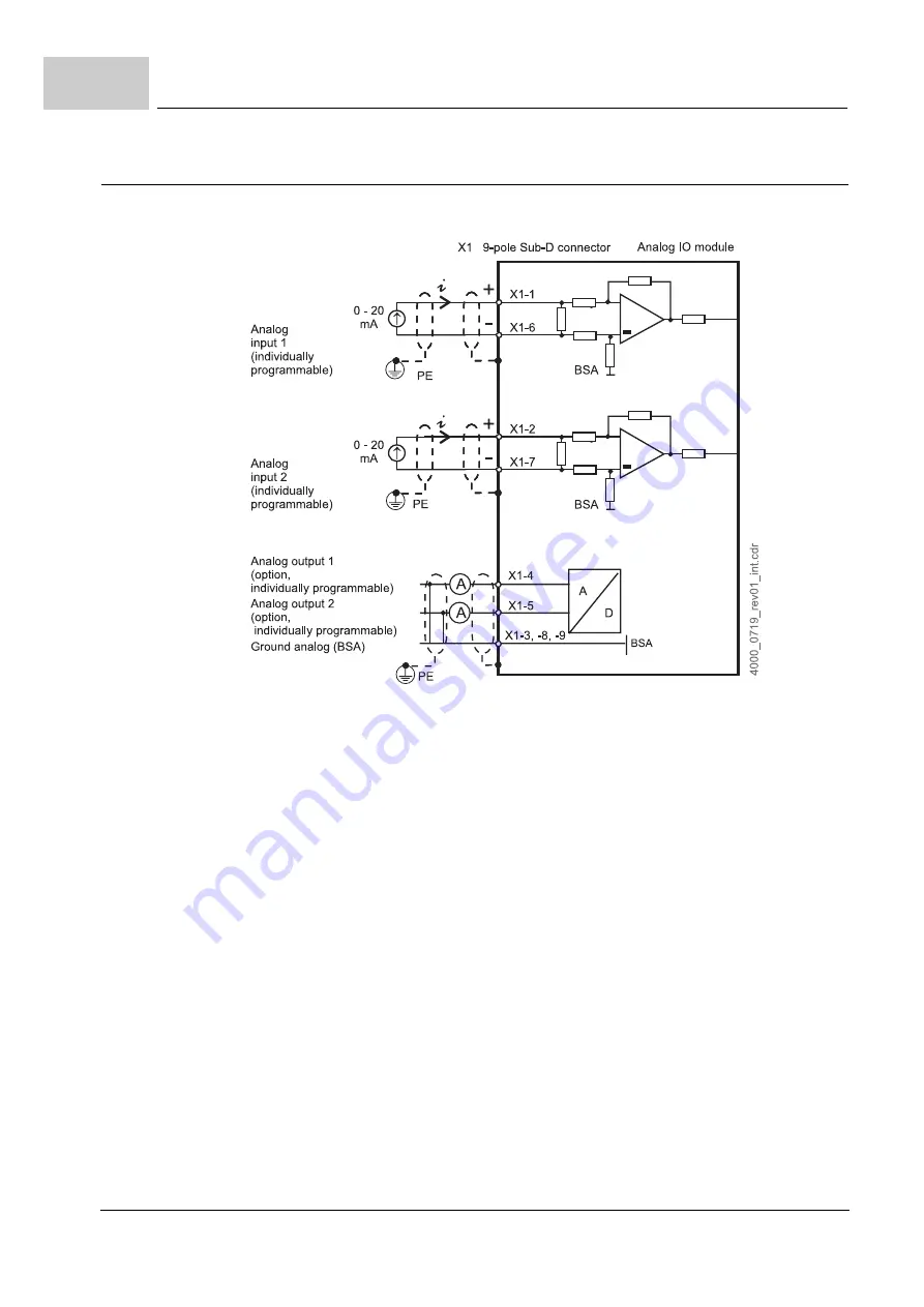
Internal circuit diagram

Instruction handbook 

b maXX


(BM4-F-)AIO-XX (Analog IO module)

Document  No.: 5.01045.08

Baumüller Nürnberg GmbH

42

of 82

7.6

7.6.2

Internal circuit diagram of Analog IO module (BM4-F-)AIO-04

Figure 9:

Internal circuit diagram of Analog IO module (BM4-F-)AIO-04

Summary of Contents for AIO Series

Page 1: ...he Manual before starting any work Language English Translation Document No 5 01045 08 Part No 372665 Status 12 Dec 2014 E 5 01045 08 b maXX BM4 F AIO XX AIO XX Analog IO module BM4400 BM4400 ES BM4600 BM4600 ES BM4700 BM4700 ES ...

Page 2: ...omments so that we can take them into account and include them when transitioning from the preliminary information to the final information as reviewed by Baumüller The conditions stipulated in the following section under Obligatory are invalid in case of pre liminary information Obligatory This Instruction handbook are a part of the equipment machine This Instruction handbook must be available to...

Page 3: ...ng 15 2 8 Safety equipment 16 2 9 Behavior in hazardous situations or at accidents 16 2 10 Signs and labels 17 3 Technical Data 19 3 1 Electrical data 19 3 2 Power input 20 3 3 Input linearity error 20 3 4 Operation conditions 20 4 Design and Operation 21 4 1 Function 22 4 2 BM F AIO XX for standard controller 23 4 2 1 Slots BM4 F AIO XX for standard controller 23 4 2 2 Type plate BM4 F AIO XX for...

Page 4: ...oning 44 8 2 1 Recognition of the Analog IO module 44 8 2 2 Testing of the Analog IO module 49 8 2 2 1 Testing of inputs AIO 01 02 and 03 50 8 2 2 2 Testing of inputs AIO 04 51 8 2 2 3 Testing of outputs 53 8 2 3 Offset adjustment of an analog input channel 55 8 2 3 1 Offset adjustment of AIO 01 02 03 55 8 2 3 2 Offset adjustment AIO 04 57 8 3 Operation 58 9 Maintenance 61 9 1 Safety notes 61 9 2 ...

Page 5: ... prerequisite for safe working is compliance with all the safety and handling in structions stated in the instruction handbook b maXX 4000 Additionally the valid accident prevention regulations and general safety regulations ap plicable to the scope of application the device must be complied with Read this Instruction handbook and the Instruction handbook b maXX 4000 particularly the safety notes ...

Page 6: ...in or der to prevent accidents personal injury and material damage Recommen dations DANGER this indicates a hazardous situation which if not avoided will result in death or se rious injury WARNING this indicates a hazardous situation which if not avoided could result in death or serious injury CAUTION this indicates a hazardous situation which if not avoided could result in minor or moderate injur...

Page 7: ...nductors grounding disconnectors overcurrent protection etc The person who carried out the mounting or installation is liable for any damage incurred when assembling or connecting the device 1 4 Copyright protection The instruction handbook must be treated confidentially It is to be used exclusively by personnel who work with the device The consignment of the instruction handbook to third persons ...

Page 8: ...aXX 4000 5 12008 chapter Disposal 1 8 Guarantee provisions The guarantee provisions are stated in a separate document of the sales documents The devices described herein may only be operated in accordance with the stipulated methods procedures and conditions Anything else not presented here including the op eration of devices in mounted positions is not permitted and must be cleared with the plant...

Page 9: ...372861 Incremental encoder emulation module BM4 F IEE XX or IEE XX 5 02020 354858 376728 SSI encoder emulation module BM4 F SIE XX or SIE XX 5 03056 377123 379049 Doc No Part No German Part No English DISC NT slave BM4 O DNT XX 5 03007 367670 CANopen slave BM4 O CAN 03 5 02014 368692 368693 CANopen slave programming handbook for controller 5 02065 368694 372860 CANopen over EtherCAT programming ha...

Page 10: ...EtherCAT slave module BM4 O ECT 01 ECT 01 5 06003 394953 394954 Ethernet with EtherCAT master for b maXX drive PLC 5 07001 407996 407997 Ethernet with EtherCAT master for b maXX drive PLC application handbook 5 07002 407998 407999 Ethernet with EtherCAT for b maXX drive PLC 5 10018 433997 POWERLINK Controlled Node BM4 O PLK 01 PLK 01 ES 5 12072 444497 444498 POWERLINK Controlled Node BM4 O PLK 01 ...

Page 11: ...orming work on or with the device must have read and understood this Instruction Handbook and the Instruction Handbook of b maXX 4000 5 12008 before working with the device This also applies if the person who is involved with this kind of device or a similar one or has been trained by the manufacturer 2 2 Changes and modifications to the device In order to prevent hazards and to ensure optimum per...

Page 12: ... hazard assessment any additional hazards that could arise from the special working conditions in the use area of the device These must then be implemented in the form of operating instructions for operation of the device m This Instruction handbooks must be kept accessible to personnel working with the de vice at all times in the immediate vicinity of the device m The specifications of the Instru...

Page 13: ...fied personnel m Qualified personnel n Electrical engineers authorized by Baumüller Nürnberg GmbH and qualified electri cians of the customer or a third party who have learned to install and maintain Baumüller drive systems and are authorized to ground and identify electrical power circuits and devices in accordance with the safety engineering standards of the com pany n Qualified personnel have h...

Page 14: ...the electrical system to be performed by qualified personnel m Switch off the current when any kind of work is being performed on the electrical system and ensure safety before switching on again DANGER Risk of fatal injury from electrical current Stored electric charge Discharge time of the system discharge time of the device with the longest DC link discharge time connected to the DC link See In...

Page 15: ...uring operation m Do not open any covering during operation m The amount of residual mechanical energy depends on the application Powered components still turn move for a certain length of time even after the power supply has been switched off Ensure that adequate safety measures are taken DANGER Risk of fatal injury from electrical current There is a risk of electric shock if an electrically cond...

Page 16: ...nd properly m Stop operation of the device immediately with an EMERGENCY Stop m Initiate first aid measures m Evacuate persons from the danger zone m Notify the responsible persons of the site m Alarm medical personnel and or the fire department m Keep access routes clear for rescue vehicles WARNING Risk of fatal injury due to non functional safety equipment Safety equipment provides for the highe...

Page 17: ...me stickers and symbols on the device can become dirty or oth erwise unrecognizable Therefore m Maintain all safety warning and operating labels on the device in easily readable condition Electrical voltage Only qualified personnel may work in work areas that identified with this Unauthorized persons may not touch working materials marked correspondingly DANGER Risk of fatal injury from electrical...

Page 18: ...Signs and labels Instruction handbook b maXX BM4 F AIO XX Analog IO module Document No 5 01045 08 Baumüller Nürnberg GmbH 18 of 82 2 10 ...

Page 19: ...it 16 bit Design differential input circuit Input resistance ca 50 kΩ ca 100 Ω Max input current 200 µA 20 mA Min input current 4 mA Sample rate inputs one input used 125 µs Sample rate inputs both inputs used 250 µs Max analog input voltage 10 V to 10 V 2 V Number of outputs 2 1 Number of IO output links 2 Max output current 1 mA Resolution 8 bit 16 bit 12 bit 16 bit Update rate fast outputs 125 ...

Page 20: ... 3 V 160 mA 40 mA 15 0 V 27 mA 37 mA 20 mA 23 mA 37 mA 15 0 V 26 mA 35 mA 19 mA 22 mA 35 mA 8 0 V DNL min DNL typ DNL max INL min INL typ INL max Offset min Offset typ Offset max Gain min Gain typ Gain max AIO 01 0 2 6 0 2 5 0 3 6 0 4 8 AIO 02 0 2 4 0 3 6 0 3 6 0 3 6 AIO 03 0 2 4 0 2 4 0 8 16 0 15 50 AIO 04 0 2 4 0 3 6 0 3 6 0 3 6 Transportation temperature range 25 C bis 70 C Transportation clima...

Page 21: ...00 The BM4 F AIO XX is designed as plug in module within the standard controller and can be replaced or upgraded The AIO XX is mounted stationary in the ES controller Power unit Controller part standard controller Design cover standard controller only BM4XXX XXX XX1XX BM4XXX XXX XX2XX BM4XXX XXX XX3XX Standard controller BM4XXX XXX XX4XX BM4XXX XXX XX5XX ES controller Controller part ES controller...

Page 22: ... the controller functionality with function and option modules e g encoder modules analog inputs outputs or field bus connections ES controller with not exchangeable function and option modules The Analog IO module is available as plug in module BM4 F AIO XX for standard con troller and as AIO XX built in the ES controller NOTE The operation with ProDrive is described only Please contact Baumüller...

Page 23: ...er 4 2 1 Slots BM4 F AIO XX for standard controller Function and option modules can be plugged in the slots of the controller part Each po sition is clearly identified by a character The Analog IO module can be plugged in following slots NOTE At the most 2 Analog IO modules can be used Plug back side Handle Module identification AIO 01 AIO 02 AIO 03 AIO 04 Sub D connector front A BM4 F AIO 02 BM4 ...

Page 24: ... XX SPS BM4 O CAN 04 CANopen master BM4 O IEI XX incremental counter module BM4 O ETH 01 Ethernet BM4 O ETH 02 Ethernet CANopen master BM4 O ECT 01 EtherCAT slave for PLC BM4 O ECT 02 Ethernet EtherCAT master BM4 O ECT 03 Ethernet EtherCAT cluster A X o o o o o B X o o o X o C o o o V o D o X X X E X X o o F Controller unit G o o o o o o o X X X X X X X H X X X X X X X o o o o o o J P P o o o o K ...

Page 25: ...ate Figure 3 Type plate BM4 F AIO XX for standard controller NOTE Only 2 analog outputs can be parametrized or linked even more than one AIO module is plugged NOTE EtherCAT option modules must not be plugged in slot J of a 3 rowed controller unit because the module can be damaged In case another BM4X X XXX plug in module is plugged in an unsuitable slot it will not operate We have made sure that n...

Page 26: ... BM4 F AIO XX YY Device family in which the plug in module can be built in BM4 F AIO XX YY Type of plug in module function module BM4 F AIO XX YY Name of plug in module Analog IO module BM4 F AIO XX YY Version plug in module No of inputs outputs 01 2 x 10 bit input 2 x 8 bit output 02 2 x 16 bit input 2 x 16 bit output 03 2 x 12 bit input 2 x 12 bit output 04 2 x 16 bit input 4 mA 20 mA 2 x 16 bit...

Page 27: ...ontroller The AIO XX is mounted stationary in the ES controller Figure 4 AIO XX for ES controller The controller is ordered with the desired function option modules these are mounted stationary exception slot H and cannot be changed Only the option module in slot H can be changed added e g AIO 02 position C AIO 01 always position E ...

Page 28: ...AIO 02 03 04 analog I O BM4 F DIO XX digital I O BM4 F FIO XX fast digital I O BM4 F IEE XX incremental encoder emulation BM4 F SIE XX SSI encoder emulation BM4 O ECT 01 EtherCAT slave for controller BM4 O PLK 01 POWERLINK Controlled Node for controller BM4 O VAR 01 VARAN slave for controller BM4 O SER XX Sercos slave for controller BM4 O PRO XX Profibus slave for controller BM4 O CAN 03 CANopen s...

Page 29: ...splay elements The LED H4 of the basic unit b maXX BM4000 respectively the emulation of the LED in ProDrive displays all device errors including the errors generated concerning the Analog IO module NOTE Only 2 analog outputs can be parametrized or linked even more than one AIO module is available BM4XXX XXX XXXXX Ryy XXXXXX XXX XX Device generation BM4XXX XXX XXXXX Ryy XXXXXX XXX XX ES controller ...

Page 30: ...Display and operation elements Instruction handbook b maXX BM4 F AIO XX Analog IO module Document No 5 01045 08 Baumüller Nürnberg GmbH 30 of 82 4 4 ...

Page 31: ...ontinuous shock class 2 M 1 as in EN 60721 3 2 5 2 Transport inspection Upon receiving the delivered goods immediately examine them for completeness and transport damage If there is outwardly visible transport damage proceed as follows m Do not accept the delivery or conditionally accept it with reservations m Note the extent of the damage on the transport documents or on the delivery note of the ...

Page 32: ...packaging of the device h Verify the delivery scope based on the delivery note File a claim with the responsible Baumüller representative if the delivery is incomplete 5 4 Disposal of the packaging The packaging consists of cardboard plastic metal parts corrugated cardboard and or wood h When disposing of the packaging comply with the national regulations NOTE Claim each individual deficiency as s...

Page 33: ... with standard controller 6 1 Preparation of mounting h Check the marking AIO XX whether the right plug in module is available Figure 5 BM4 F AIO XX for standard controller h Determine the suitable slot see ZSlots BM4 F AIO XX for standard controller on page 23 NOTE The AIO XX modules are mounted stationary in the BM4400 BM4600 BM4700 with ES controller and cannot be changed therefore no mounting ...

Page 34: ...aulty mount ing can lead to life threatening situations or substantial material damage Therefore m Only allow mounting to be performed by employees of the manufacturer or by oth er qualified personnel DANGER Risk of fatal injury from electrical current There is an immediate risk of fatal injury if live electrical parts are contacted Therefore m Switch off the current when any kind of work is being...

Page 35: ...ce sensible latches tightly into the end position 9 Turn the twist lock beyond and beneath by 90 into the vertical position locking posi tion 10 Connect cable of the BM4 F AIO XX module with the Sub D connector 11 Put the design cover on the device again Thus the mounting of the BM4 F AIO XX is completed NOTICE Note electrostatic discharge The BM4 F AIO XX contains ESD sensible parts Therefore m R...

Page 36: ...Assembly Instruction handbook b maXX BM4 F AIO XX Analog IO module Document No 5 01045 08 Baumüller Nürnberg GmbH 36 of 82 6 2 ...

Page 37: ...f the current when any kind of work is being performed on the electrical system and ensure safety before switching on again m Pay attention to the relevant safety instructions when handling electrical equip ment carrying high voltages m Do not touch electrically live parts before taking into account the discharge time of the capacitors WARNING Danger because of faulty installation and initial comm...

Page 38: ...connection of the Analog IO module it can be damaged destroyed m Ensure that the electrical power connection parameters as specified in the techni cal data are adhered to and that the connections are made in accordance with the instructions m Avoid short circuit between input points and output points In the event of a short circuit between input points and output points the Analog IO module may ge...

Page 39: ...ument No 5 01045 08 39 of 82 7 7 4 Connection diagrams Figure 7 Connection diagram Analog IO module Standard controller ES controller Pin assignment Pin No Assignment Sub D connector 9 pole 1 IN 1 2 IN 2 3 OUT 1 OUT 2 4 OUT 1 5 OUT 2 6 IN 1 7 IN 2 8 OUT 1 OUT 2 9 OUT 1 OUT 2 ...

Page 40: ...le connector of the Analog IO module cable goes downwards 4 Replace the cover again if necessary 5 Laying of the cable in the control cabinet refer to ZRequirements on the electrical con nection auf Seite 38 DANGER Risk of fatal injury from electrical current There is an immediate risk of fatal injury if live electrical parts are contacted Therefore m Switch off the current when any kind of work i...

Page 41: ...b maXX BM4 F AIO XX Analog IO module Document No 5 01045 08 41 of 82 7 7 6 Internal circuit diagram 7 6 1 Internal circuit diagram of Analog IO Modules BM4 F AIO 01 02 03 Figure 8 Internal circuit of Analog IO module BM4 F AIO 01 02 03 ...

Page 42: ... handbook b maXX BM4 F AIO XX Analog IO module Document No 5 01045 08 Baumüller Nürnberg GmbH 42 of 82 7 6 7 6 2 Internal circuit diagram of Analog IO module BM4 F AIO 04 Figure 9 Internal circuit diagram of Analog IO module BM4 F AIO 04 ...

Page 43: ...ctly cabled m The connection must be suitable to the electrical specification of the Analog IO module 3 The switching cabinet is properly closed and all safety devices are put into operation 4 The b maXX 4000 is ready for use 8 1 Safety notes Basics WARNING Risk of injury due to improper operation Improper operation can lead to severe personal injury or material damage Therefore m Perform all oper...

Page 44: ...ually existing in the b maXX BM4000 These errors might have been caused by faulty assembly e g defective cable or some mistake s in installation e g supply voltage absent Only after having corrected the er rors the commissioning can be continued NOTICE Environmental conditions that do not meet the requirements Environmental conditions that are non compliant can lead to property damage Therefore m ...

Page 45: ...Commissioning Operation Instruction handbook b maXX BM4 F AIO XX Analog IO module Document No 5 01045 08 45 of 82 8 3 Open with ProDrive the window Diagnosis Figure 10 ProDrive navigation ...

Page 46: ...dditionally 5 Decide on the basis of the display Figure 11 ProDrive Service m If the Analog IO module has been correctly recognized the commissioning can be continued refer to Instruction Handbook b maXX 4000 5 12008 or Parameter Man ual b maXX 4000 5 03039 m If the Analog IO module has not been correctly recognized turn off the device check the mounting and the installation After removing all err...

Page 47: ...7 of 82 8 6 Icon ProDrive Navigation 7 Configuration submenu IO analog inputs Figure 12 ProDrive navigation submenu IO analog inputs 8 The submenu contains Analog input link 1 and 2 e g choose Analog input link 1 The window Analog input link 1 is opened The inputs can be selected in the center of the window ...

Page 48: ... Only if there is no message under the scale the AIO XX or BM4 F AIO XX is rec ognized properly and can be used m If the AIO XX or BM4 F AIO XX is not recognized then switch off the device and check the assembly installation After having removed all errors restart the device for checking whether the plug in module gets recognized properly now m If the Analog IO module is not recognized yet then it...

Page 49: ...r m AIO 04 Current range of 0 20 mA can be set by a current calibrator Motor for speed set clockwise or counter clockwise has been connected shaft ends are rotating freely h ProDrive Navigation Diagnosis submenu Service h Check in the menu Service whether the Analog IO Module has been correctly rec ognized e g in the line for the slot D NOTICE Notice electrostatic discharge The BM4 F AIO XX or the...

Page 50: ...n ProDrive Figure 15 Analog input link 1 AIO 01 02 and 03 3 By clicking on the g symbol select the entry Input D 1 D module in position D 1 input 1 from the drop down list Figure 16 Input selection AIO 01 02 and 03 4 Enter in menu analog input link 1 m Target parameter number 1171 ramp function generator input m Smoothing time 10 ms m Scaling factor 1 m Offset 0 m Threshold 0 A scale is displayed ...

Page 51: ...kwise running 6 Repeat the above steps for the input 2 8 2 2 2 Testing of inputs AIO 04 1 ProDrive Navigation IO analog inputs 2 Select Analog input link 1 in ProDrive Figure 17 Analog input link 1 AIO 04 NOTE If for example the scale shows 0 V even though there is an analog voltage applied on input 1 see pin assignment ZConnection diagrams on page 39 then the input is defective When changing the ...

Page 52: ... input m Smoothing time 10 ms m Scaling factor 1 m Offset 0 m Threshold 0 A scale is displayed and shows the applied current set by the current calibrator e g 12 mA 5 Check the display in Analog input link 1 The RPM of the motor can be regulated now by the current calibrator 6 Repeat the above steps for the input 2 NOTE If for example the scale shows 0 mA even though there is a current applied on ...

Page 53: ...IO XX Analog IO module Document No 5 01045 08 53 of 82 8 8 2 2 3 Testing of outputs Note the ZPre conditions on page 49 1 Select in ProDrive IO analog outputs Figure 19 Analog output link 2 Select submenu Analog output link 1 Figure 20 Menu Analog output link 1 ...

Page 54: ...ing factor 1638 Dig V The voltage at the output point D 1 see pin assignment ZConnection diagrams on page 39 can be measured now by using the suitable measuring instrument If 10 V has been applied at the input D 1 then there will also be an output voltage of 10 V at the analog output 5 Repeat the test for output 2 With that testing of the Analog IO Module is complete NOTE If no voltage can be meas...

Page 55: ...pin for analog inputs 1 and 2 and connection for the voltmeter n Sub D connector 9 pin with inputs 1 and 2 short circuited Pin assignment see ZConnection diagrams on page 39 n Computer with ProDrive Offset adjustment within the analog input link Set 16 Bit application parameter as target for the analog input link Example Target parameter P3333 Read the value in ProDrive while input is short circui...

Page 56: ...eter 9 235 V Read value in ProDrive 29295 Conversion of read value into voltage Gain to be set 1 03 Check Input short circuited No of increments 20 Connect voltage supply Convert connected voltage to increments No of increments The adjustment of an analog input channel of the AIO 01 AIO 02 and AIO 03 is complet ed now read value 10 V 32767 29295 10 V 32767 8 940 V connected measured voltage read v...

Page 57: ...rameter P3333 Read the value in ProDrive while input is open 0 mA Example 179 increments Offset adjustment Example offset adjustment value to be set 0 273 Gain adjustment within the analog input link Connection 10 mA Measured current amperemeter 10 000 mA Read value in ProDrive 32900 Conversion of read value into current Gain to be set 0 996 NOTE All settings must be done when controller state is ...

Page 58: ... ProDrive The procedure for Analog input Link 1 is described below via an example The proce dure for Analog output Link 2 and the analog outputs is similar 1 Start ProDrive 2 Click ProDrive Navigation 3 Click on IO analog inputs path Device configuration IO analog inputs Abbildung 22 ProDrive Navigation 4 Click on Analog input link 1 5 Now open the menu Analog input 1 with the data for one of the ...

Page 59: ...l for opening the parameter list 7 Click on the symbol before Configuration IO analog in the window Parameter list The corresponding parameters of the Analog IO module are displayed Figure 23 Configuration parameter list NOTE The error parameters of the Analog IO Modules can be found in the chapter ZError messages from page 69 ...

Page 60: ...Operation Instruction handbook b maXX BM4 F AIO XX Analog IO module Document No 5 01045 08 Baumüller Nürnberg GmbH 60 of 82 8 3 ...

Page 61: ...ed environmental conditions are m Dust free environmental air m Temperature Min 5 C to max 55 C m Relative humidity 5 to 85 no condensation m Installation altitude From 1000 m and higher derating WARNING Risk of injury due to improperly performed maintenance work Improper maintenance can lead to severe personal injury and material damage Therefore m Before beginning work make sure that there is en...

Page 62: ...GmbH 62 of 82 9 3 9 3 Inspection intervals maintenance notes Refer to Instruction handbook b maXX 4000 5 12008 9 4 Repairs In case of device damage please inform your sales office or Baumüller Nürnberg GmbH Ostendstr 80 90 90482 Nuremberg Germany Tel 49 9 11 54 32 0 Fax 49 9 11 54 32 1 30 Mail mail baumueller de Internet www baumueller de ...

Page 63: ...t are energized with hazardous voltage Therefore m Pay heed to areas on the device that could be dangerous WARNING Risk of injury due to improper fault correction Therefore m Only qualified personnel may work on this device m Personnel that work with the b maXX device must be trained in the safety regula tions and the handling of the device and be familiar with the correct operation of it In parti...

Page 64: ... displayed code the error message can be determined The displayed error is with out exception an LEVEL 2 error P0201 P0216 The display of an error code starts by displaying F for 1 5 s Then the four characters of the error code are displayed The separate characters are displayed for about 0 8 s in terrupted by a short break If there are other errors these are displayed in the same man ner The proc...

Page 65: ... error message is shown in the operating software h Start the operating program ProDrive from FW 3 07 if it isn t running yet Display the error message in ProDrive h Open navigation with click on in front of Management Figure 25 ProDrive navigation NOTE The controller software version and the operating software version must be compat ible to use ProDrive with all functions ...

Page 66: ...rical order The newly occurring messages are added to the end of the list when communication is active Figure 26 Drive manager ProDrive NOTE If you are not able to start the motor although the red LED H4 is not lighting up and although the LED H2 is lighting up green check the parameterization of the b maXX 4000 with the parameter list in ProDrive Error possibilities are e g torque limit 0 has bee...

Page 67: ... an error response of the drive are saved chronologically in this error memory A read access to the error memory is done element by element with an index parameter P0258 and a value parameter P0259 The error memory will be deleted completely at error acknowledgment Bit 7 1 in control word For a further description see parameter P0257 in the Parameter Manual Error display If an error appears the ac...

Page 68: ...erated in bit 7 generated by the control system or by operating software via input to parameter list Note The drive control must be active see parameter P1001 Communication source for the selected communication source m Via a digital input A digital input of a DIO module can be selected via parameter P0575 Digital input for error acknowledgement for error reset A rising edge on this input resets t...

Page 69: ...ult correction Instruction handbook b maXX BM4 F AIO XX Analog IO module Document No 5 01045 08 69 of 82 10 10 3 2 Error messages Figure 28 Survey error list The error messages are displayed in ProDrive window Drive manager ...

Page 70: ...nd level error messages are displayed on the 7 segment display in ProDrive In the column Reaction the reaction of the system to the error is shown m pulse stop inhibit pulses m adjustable the error reaction can be set via ProDrive Window Drive management toolbar button Error reaction m no reaction means the drive is continuing to work and the red error LED is blinking 2nd level error messages P020...

Page 71: ...l output short circuited or 24V supply not connected to the DIO module no reaction Check the cabling of the digital outputs 4 Invalid target parameter value caused by digital input no reaction Check the parameterization of the input channel 5 Direct PLC IO access for this module not per mitted no reaction Don t select the module 6 Required module is missing only for BM4100 active mains rectifier u...

Page 72: ...Error handling Instruction handbook b maXX BM4 F AIO XX Analog IO module Document No 5 01045 08 Baumüller Nürnberg GmbH 72 of 82 10 3 ...

Page 73: ...me of the device with the longest DC link discharge time in the DC link connection Refer to Instruction handbook b maXX BM4000 Electrical data Therefore m Do not touch before taking into account the discharge time of the capacitors and electrically live parts m Heed corresponding notes on the equipment m If additional capacitors are connected to the DC link the DC link discharge can take a much lo...

Page 74: ...safety regulations m Take heed of any special local regulations If you are unable to directly ensure safe disposal yourself commission a suitable disposal contractor m In the event of a fire hazardous substances could possibly be generated or re leased m Do not expose electronic components to high temperatures m Beryllium oxide is used as inner insulation for example for various power semicon duct...

Page 75: ...75 of 82 Instruction handbook b maXX BM4 F AIO XX Analog IO module Document No 5 01045 08 APPENDIX A DECLARATION OF CONFORMITY ...

Page 76: ...pliance to the guidelines require a correct assembly of the products and the careful attention of the associated instruction handbooks of BM4000 and of BM4 F AIO XX Analog IO Module The compliance to the above mentioned guidelines are checked on the basis of typical BM4000 controller configurations Nürnberg 25 Sep 2012 Place Date The content of the Declaration of Conformity is subject to change Th...

Page 77: ...O 01 02 03 41 Internal circuit diagram of Analog IO module BM4 F AIO 04 42 ProDrive navigation 45 ProDrive Service 46 ProDrive navigation submenu IO analog inputs 47 Analog input link 1 48 Module not existent 48 Analog input link 1 AIO 01 02 and 03 50 Input selection AIO 01 02 and 03 50 Analog input link 1 AIO 04 51 Input selection AIO 04 52 Analog output link 53 Menu Analog output link 1 53 Outpu...

Page 78: ...Instruction handbook b maXX BM4 F AIO XX Analog IO module Document No 5 01045 08 Baumüller Nürnberg GmbH 78 of 82 Table of figures ...

Page 79: ... Guarantee provisions 8 H Hazardous situations 16 Hazards special 14 I Initial commissioning 37 Inspection 62 Inspection intervals 62 Installation 37 Installation procedure 40 Internal circuit diagram 41 42 K Key to symbols 6 L LED H2 66 LED H4 66 Limitation of liability 7 M Maintenance 61 Malfunctions behavior 63 Modifications 11 N Note 6 O Operating instructions contents 11 Operating personnel 1...

Page 80: ...chnical data 19 Temperature range 20 Testing of inputs 50 51 Transport inspection 31 Troubleshooting 63 Twist lock 35 Type code ES controller 29 Standard controller 26 Type of plug in module 26 Type plate ES controller 29 Standard controller 25 U Unpacking 32 Use compliant with indented purpose 12 W Warning 6 Warning notes 6 ...

Page 81: ...le Document No 5 01045 08 81 of 82 Revisionsübersicht Overview of Revisions Version Status Changes 5 01045 06 25 09 2012 Revision because of AIO 04 new design 5 01045 07 13 03 2014 Revision ES controller troubleshooting 5 01045 08 12 12 2014 Troubleshooting ...

Page 82: ...Instruction handbook b maXX BM4 F AIO XX Analog IO module Document No 5 01045 08 Baumüller Nürnberg GmbH 82 of 82 Notes ...

Page 83: ......

Page 84: ... our permanent revision service Please notice that specifications data information are current values according to the printing date These statements are not legally binding according to the measurement computation and calculations Before you make any information given in this manual to the basis of your own calculations and or applications please make sure that you have the latest edition of the ...

Reviews: