19
4.3 Operation
4.3.1 Using the standard LED panel
4.3.1.1 Start Up in Normal AC Mode
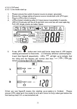
1. Before commencing ensure that the grounding is connected properly.
2. Ensure that the utility voltage matches the input voltage window of the
UPS.
3. Connect the UPS main power cord into the utility AC power source
receptacle.
4. Switch on the AC power source. All of the LEDs on the front panel display
will flash once after five seconds. At the same time, the fan at the front of
the UPS will start operating.
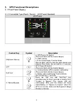
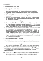
5. Press and hold the ON button ‘
’ for approximately one second to start
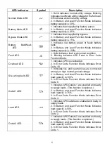
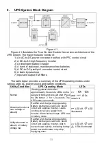
the UPS. The buzzer will beep and the LED indicators "
" ,"
","
"and
"
" will shine after 1-5 seconds. The start-up procedure is now completed,
and the UPS outlets are ready to supply power to the load.
6. It is advisable to perform a battery mode test before connecting the loads to
the UPS to ensure that the batteries are working properly. To do this,
switch off the AC power source when the UPS is on. The
LED on the
front panel display will turn off, the
LED will shine, and the buzzer will
pulsate, indicating that the UPS is in Battery Mode. Connect a non-critical
load to the UPS outlets to confirm that the batteries are supplying power.
Repeat the test by switching on and off the AC power source to ensure that
the UPS is functioning properly.
4.3.1.2 Start-up in Battery Mode (Cold Start)
This UPS can be switched on without the presence of an AC power source.
Press and hold the ON button ‘
’ until the buzzer beeps. Release and
then within the next 10 seconds press and hold the same button a second time.
The UPS will perform its start-up procedure. The LEDs "
" ,"
","
"and "
" will shine after 1-5 seconds, and the buzzer will pulsate to indicate
successful power-on.
Note: Ensure that the UPS batteries are pre-charged for at least four hours
by simply connecting the AC power cord to the utility receptacle.
Summary of Contents for BBP-AR-1000RM-PSW-ONL
Page 1: ...1 1 5 2 2 and 3 kVA Intelligent True On Line UPS For Corporate and IT Users User Manual...
Page 17: ...16 4 1 1 Installation Instructions Tower installation Rack Mount installation Step 1 Step 2...
Page 18: ...17 Step 3...
Page 25: ...24 J K L M...
Page 29: ...28 V1 The UPS is operating in normal mode...
Page 40: ...39 Please refer to the software user s manual...


