


Assembly and Operation
A: R82GB0EA.PMD
B: R82DE0EA.PMD
E: 170403 /T. Wenger
G: 020403 / TCS
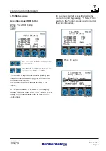
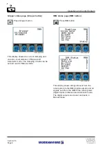
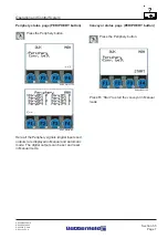
Section - 5
Page - 7
?
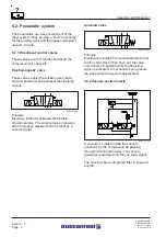
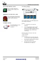
LS5100 transceiver
24 V DC power supply
(See circuit diagram for details of connections)
The two K bus LEDs indicate the operating
statuses of the bus terminals and the
connections to them.
Green LED illuminated: In operation, no faults.
Red LED flashing. Fault signal. Two different
frequencies.
Faults are coded as follows:
Description:
0
EEPROM check sum fault
1
Inline Code Buffer overrun
2
Unknown data type
Description:
Programmed configuration
Incorrect table entry / bus coupler Table
comparison (Terminal ”n”) incorrect
Description:
Terminal bus command fault
Description:
Terminal bus data error: Breakage behind
Terminal ”n” (0: coupler)
Fast flashing
Error code start
1st. slow sequence
Error code
2nd. slow sequence
Error cause
R8B2_GB018.XLS
Error code
Error cause
1 pulse
0 1 2
R8B2_GB154.XLS
Error code
Error cause
2 pulse
0 n(n>0)
R8B2_GB155.XLS
Error code
Error cause
3 pulse
0
R8B2_GB156.XLS
Error code
Error cause
4 pulse
0 n
R8B2_GB157.XLS
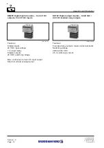
Address
selector
V+
Transceiver
supply
V -
Shield
Power contacts
K bus
R8B2_017.PDF
Configuration
interface
right: CAN-L
left: Field bus LED
right: C bus LED
left: CAN-H
Summary of Contents for UNILOG B2
Page 4: ...A PB2GBI1A P65 B PB2DEI1A P65 E 180202 Ruder G 190202 G Krajnik Section IN1 Page 2 Index...
Page 10: ......
Page 14: ...A R82GB0AA PDM B R82DE0AA PDM E 080403 T Wenger G 020403 TCS Section 1 Page 4 General...
Page 16: ...A R82GB0AA PDM B R82DE0AA PDM E 080403 T Wenger G 020403 TCS Section 1 Page 6 General...
Page 32: ...A R82GB0CA PDM B R82DE0CA PDM E 080403 T Wenger G 020403 TCS Section 3 Page 10 Specifications...
Page 118: ...A R82GB0HA PMD B R82DE0HA PMD E 080403 T Wenger G 020403 TCS Section 7 Page 16 Maintenance...