


S = S
i
+ Slope Margin
S = 29% + 10% = 39%
Calculate Offset Current I
Step 3.
ugh current loading so it tends to offset the operating slope S
i
upward from the origin. Thus, it decreases the safety arg
ial tripping
characteristic knee point (intersection of the minimum pickup tripping characteristic and the
slope-tripping characteristic).
I
OFFSET
= IE + I
unmon
I
OFFSET
= 0.24 + 0 = 0.24
where:
IE
is assumed less than 4% of the self-cooled rating.
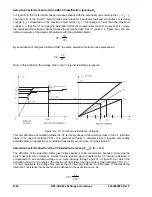
OFFSET
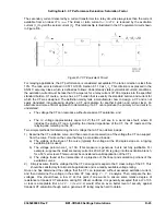
. The margin at the knee point of the tripping characteristic is
illustrated in Figure D-2. The additional mismatch caused by excitation current and unmonitored
loads does not vary with thro
m
in at the different
9365200990 Rev F
BE1-CDS240 Settings Calculations
D-19
cooled
forced
MVA
cooled
self
MVA
024
0
20
12
IE
IE
X
cooled
self
*
*
1
04
0
IE
.
*
*
.
where:
-34.
I
unmon
is the unmonitored load calculated in
Calculate Minpu,
Step 2, Equation D-35.
Step 4. Calculate Operating Margin M
o
. The Operating Margin M
o
is given by this equation:
X
is the tap conversion factor defined in
Calculate Minpu,
Step 1, Equation D
OFFSET
i
o
I
S
Minpu
M
1
S
The conservative calculation of margin at the knee point uses
S
i
as calculated in
Calculate Slope
, Step 1.
For this example,
M
o
in times tap is the following equation:
tap
times
040
.
0
024
.
0
39
1
*
25
.
0
M
o
29
The above calculation of margin is conservative. For the low current level where the margin at the tripping
characteristic knee point is of interest, the CT error will typically be less than 1%. Thus, calculating the
margin using
S
I
= 20 (replace 10% CT error with 1% CT error) yields the following result in this equation:
tap
times
098
0
024
0
39
o
20
1
25
0
M
.
.
*
.
Step 5. Convert the margin to primary amperes. As a reality check, convert the margin to high side and
low side primary amperes.
If the conservative calculation yielded a margin less than or equal to 0, the minpu and/or the slope
settings should be increased.
The equation to do so is similar to the equation in the middle of page
D-16.
4
16
60
1
79
2
098
0
Ipri
.
*
.
*
.
amps @ 69 kV
8
90
1
160
79
5
098
0
*
.
*
.
Ipri
.
amps @ 12.47 kV
The recommended harmonic restraint settings have been in effect successfully for many years. Most
applications should use these settings. When second harmonic sharing is enabled, restraint for the A
phase differential element is determined by:
Harmonic Restraint Settings
Summary of Contents for BE1-CDS240
Page 2: ......
Page 8: ...vi BE1 CDS240 Introduction 9365200990 Rev F This page intentionally left blank ...
Page 38: ...1 28 BE1 CDS240 General Information 9365200990 Rev F This page intentionally left blank ...
Page 40: ...ii BE1 CDS240 Quick Start 9365200990 Rev F This page intentionally left blank ...
Page 152: ...ii BE1 CDS240 Metering 9365200990 Rev F This page intentionally left blank ...
Page 226: ...iv BE1 CDS240 Application 9365200990 Rev F This page intentionally left blank ...
Page 286: ...ii BE1 CDS240 Security 9365200990 Rev F This page intentionally left blank ...
Page 290: ...9 4 BE1 CDS240 Security 9365200990 Rev F This page intentionally left blank ...
Page 292: ...ii BE1 CDS240 Human Machine Interface 9365200990 Rev F This page intentionally left blank ...
Page 306: ...10 14 BE1 CDS240 Human Machine Interface 9365200990 Rev F This page intentionally left blank ...
Page 308: ...ii BE1 CDS240 ASCII Command Interface 9365200990 Rev F This page intentionally left blank ...
Page 342: ...11 34 BE1 CDS240 ASCII Command Interface 9365200990 Rev F This page intentionally left blank ...
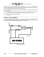
Page 349: ...Figure 12 5 Horizontal Rack Mount Front View 9365200990 Rev F BE1 CDS240 Installation 12 5 ...
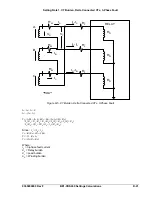
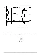
Page 361: ...Figure 12 17 Typical DC Connection Diagrams 9365200990 Rev F BE1 CDS240 Installation 12 17 ...
Page 372: ...12 28 BE1 CDS240 Installation 9365200990 Rev F This page intentionally left blank ...
Page 468: ...13 92 BE1 CDS240 Testing and Maintenance 9365200990 Rev F This page intentionally left blank ...
Page 512: ...14 42 BE1 CDS240 BESTCOMS Software 9365200990 Rev F This page intentionally left blank ...
Page 544: ...ii BE1 CDS240 Terminal Communication 9365200990 Rev F This page intentionally left blank ...
Page 550: ...ii BE1 CDS240 Settings Calculations 9365200990 Rev F This page intentionally left blank ...
Page 578: ...D 28 BE1 CDS240 Settings Calculations 9365200990 Rev F This page intentionally left blank ...
Page 579: ......