


Since the
X
tap values are based upon the forced cooled rating
and adjusted if necessary by the factor
calculated in
Calculate Minpu,
Step 1, equation at the top of this page. The pickup can be calculated by
the following equation:
9365200990 Rev F
BE1-CDS240 Settings Calculations
D-17
cooled
forced
MVA
X
URO
*
*
6
cooled
self
MVA
20
*
1
*
6
URO
12
6
.
3
URO
This
URO
value (3.6 rounded up to 4
step will determine the value required
.0) is the minimum setting to avoid tripping during inrush. The next
to avoid tripping for the maximum external fault under worst case
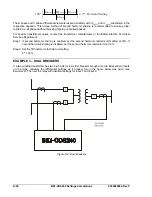
tep 1. Calculate the maximum external fault (IE) in multiples of tap. Use these two equations.
For wye connected CT’s
For delta connected CT’s (See Setting Note 2)
CT saturation.
Calculate Maximum External Fault
S
Fau
Maximum
Tap
lt
IE
phase
Fault
3
Tap
Maximum
IE
3
*
Equation D-38
Equation D-39
69 kV Side
12.47 kV Side
5
.
11
79
.
2
60
1916
IE
4
.
11
79
.
5
160
10603
IE
S
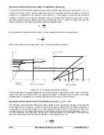
The transient monitor function provides security from tripping for external through faults by
doubling the unrestrained unit pickup setting when saturation is detected. Calculate the
unrestrained pickup such that
2 times the unrestrained pickup is greater than 70%
tep 2.
of the
maximum external through fault
in times tap. This calculation assumes that the CTs carrying
the maximum fault saturate severely, yielding only 30% of the expected ratio current. This leaves
70% of the fault current as false differential current.
02
4
2
URO
.
5
11
.
*
70
0
.
99
3
2
URO
.
Step 3. Select the unrestrained pickup setting. Choose the larger
4
11
70
0
.
*
.
of the unrestrained pickup values
and above two equations. Round the result up to the
Step 4. Convert pickup setting to primary amperes.
kup sensitivity to high side and low side
The equation to do so is similar to the equation in the middle of page D-16.
calculated in the first equations on this page
next integer value. (In the first
URO
equation above, because 4.02 is very close to 4.0, do not round up
to 5.) This results in a setting of
URO = 4 times tap
for this example.
As a reality check, convert the unrestrained pic
primary amperes.
670
706
,
3
1
160
*
79
.
5
*
4
Ipri
60
*
79
.
2
*
4
1
Ipri
amps @ 69 KV
amps @ 12.47 KV
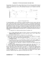
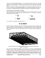
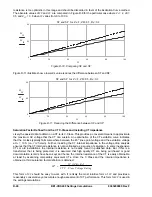
us the restraint current (
I
restraint
) that will cause a trip. The
percentage differential characteristic can operate on a slope setting that is a percent of the maximum of
the through currents or a percent of the average of the through currents.
Calculate Slope
The percentage restrained tripping characteristic is defined by the slope ratio. The slope setting S is the
ratio of the differential current (
I
op
) vers
Summary of Contents for BE1-CDS240
Page 2: ......
Page 8: ...vi BE1 CDS240 Introduction 9365200990 Rev F This page intentionally left blank ...
Page 38: ...1 28 BE1 CDS240 General Information 9365200990 Rev F This page intentionally left blank ...
Page 40: ...ii BE1 CDS240 Quick Start 9365200990 Rev F This page intentionally left blank ...
Page 152: ...ii BE1 CDS240 Metering 9365200990 Rev F This page intentionally left blank ...
Page 226: ...iv BE1 CDS240 Application 9365200990 Rev F This page intentionally left blank ...
Page 286: ...ii BE1 CDS240 Security 9365200990 Rev F This page intentionally left blank ...
Page 290: ...9 4 BE1 CDS240 Security 9365200990 Rev F This page intentionally left blank ...
Page 292: ...ii BE1 CDS240 Human Machine Interface 9365200990 Rev F This page intentionally left blank ...
Page 306: ...10 14 BE1 CDS240 Human Machine Interface 9365200990 Rev F This page intentionally left blank ...
Page 308: ...ii BE1 CDS240 ASCII Command Interface 9365200990 Rev F This page intentionally left blank ...
Page 342: ...11 34 BE1 CDS240 ASCII Command Interface 9365200990 Rev F This page intentionally left blank ...
Page 349: ...Figure 12 5 Horizontal Rack Mount Front View 9365200990 Rev F BE1 CDS240 Installation 12 5 ...
Page 361: ...Figure 12 17 Typical DC Connection Diagrams 9365200990 Rev F BE1 CDS240 Installation 12 17 ...
Page 372: ...12 28 BE1 CDS240 Installation 9365200990 Rev F This page intentionally left blank ...
Page 468: ...13 92 BE1 CDS240 Testing and Maintenance 9365200990 Rev F This page intentionally left blank ...
Page 512: ...14 42 BE1 CDS240 BESTCOMS Software 9365200990 Rev F This page intentionally left blank ...
Page 544: ...ii BE1 CDS240 Terminal Communication 9365200990 Rev F This page intentionally left blank ...
Page 550: ...ii BE1 CDS240 Settings Calculations 9365200990 Rev F This page intentionally left blank ...
Page 578: ...D 28 BE1 CDS240 Settings Calculations 9365200990 Rev F This page intentionally left blank ...
Page 579: ......