


OFFSET
i
o
OFFSET
o
o
I
S
S
minpu
M
I
S
minpu
S
minpu
M
AC
AB
M
1
i
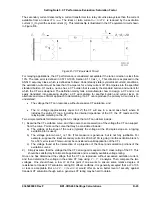
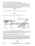
Figure D-2. Slope and Operating Margin
Step 2. Choose slope setting S. The tripping slope S must be greater than S
i
to provide a safety margin
at
the differential tripping characteristic knee point (intersection of the minimum pickup tripping
characteristic and the slope tripping characteristic). This safety margin is required to
accommodate the additional mismatch caused by the excitation current and the unmonitored load
current. Refer to Figure D-2. A
slope margin of 10%
is recommended.
S = S
i
+ Slope Margin
S = 29% + 10% = 39%
Step 3. Calculate Offset Current I
OFFSET
. The margin at the knee point of the tripping characteristic is
illustrated in Figure D-2. The additional mismatch caused by excitation current and unmonitored
loads does not vary with through current loading so it tends to offset the operating slope S
i
up-
ward from the origin. Thus, it decreases the safety margin at the differential tripping characteristic
knee point (intersection of the minimum pickup tripping characteristic and the slope tripping
characteristic). The offset current is calculated as:
unmon
Exc
Offset
I
I
I
Assume for the example that excitation current is 4% of full load current on the self-cooled basis.
Converting over to percent on the same MVA basis that the tap setting was chosen and including
the previously discussed
X
factor:
cooled
forced
MVA
cooled
self
MVA
*
X
*
cooled
self
IE
IE
024
.
0
20
12
*
1
*
04
.
0
IE
where:
X
is the tap conversion factor defined in
Calculate Minpu,
Step 1 (equation, page D-7).
I
unmon
is the unmonitored load calculated in
Calculate Minpu,
Step 2 (equation, page D-7.
D-10
BE1-CDS240 Settings Calculations
9365200990 Rev F
Summary of Contents for BE1-CDS240
Page 2: ......
Page 8: ...vi BE1 CDS240 Introduction 9365200990 Rev F This page intentionally left blank ...
Page 38: ...1 28 BE1 CDS240 General Information 9365200990 Rev F This page intentionally left blank ...
Page 40: ...ii BE1 CDS240 Quick Start 9365200990 Rev F This page intentionally left blank ...
Page 152: ...ii BE1 CDS240 Metering 9365200990 Rev F This page intentionally left blank ...
Page 226: ...iv BE1 CDS240 Application 9365200990 Rev F This page intentionally left blank ...
Page 286: ...ii BE1 CDS240 Security 9365200990 Rev F This page intentionally left blank ...
Page 290: ...9 4 BE1 CDS240 Security 9365200990 Rev F This page intentionally left blank ...
Page 292: ...ii BE1 CDS240 Human Machine Interface 9365200990 Rev F This page intentionally left blank ...
Page 306: ...10 14 BE1 CDS240 Human Machine Interface 9365200990 Rev F This page intentionally left blank ...
Page 308: ...ii BE1 CDS240 ASCII Command Interface 9365200990 Rev F This page intentionally left blank ...
Page 342: ...11 34 BE1 CDS240 ASCII Command Interface 9365200990 Rev F This page intentionally left blank ...
Page 349: ...Figure 12 5 Horizontal Rack Mount Front View 9365200990 Rev F BE1 CDS240 Installation 12 5 ...
Page 361: ...Figure 12 17 Typical DC Connection Diagrams 9365200990 Rev F BE1 CDS240 Installation 12 17 ...
Page 372: ...12 28 BE1 CDS240 Installation 9365200990 Rev F This page intentionally left blank ...
Page 468: ...13 92 BE1 CDS240 Testing and Maintenance 9365200990 Rev F This page intentionally left blank ...
Page 512: ...14 42 BE1 CDS240 BESTCOMS Software 9365200990 Rev F This page intentionally left blank ...
Page 544: ...ii BE1 CDS240 Terminal Communication 9365200990 Rev F This page intentionally left blank ...
Page 550: ...ii BE1 CDS240 Settings Calculations 9365200990 Rev F This page intentionally left blank ...
Page 578: ...D 28 BE1 CDS240 Settings Calculations 9365200990 Rev F This page intentionally left blank ...
Page 579: ......