


NOTE:
3 FACTOR
When calculating the tap adjust settings for the BE1-87T, the
3 COMPn factor had to be included
rega
ing the CTs in delta or by using
rdless of whether phase compensation was done by connect
internal delta compensation. The BE1-CDS240 relay does not magnify the secondary current when
performing the phase compensation internally. (For more information, see the
Internal
Compensation Chart
under the SG-CT command in Section 3.) The COMP factor is 1 unless the
CTs are connected in Delta. The BE1-CDS240 automatically takes the
3 factor into account prior
to the tap adjustment when internal phase compensation is applied to a set of CT input currents.
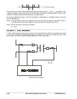
Step 2. Calculate ideal tap values. Since all CTs are wye connected, COMP1, COMP2 and COMP3 are 1
ors being reset, it would be safer to use the system nominal values
per Table D-2. Ideally, the actual transformer voltage ratings at the in-use tap position are used
for the KV Base. However, if the taps in the protected transformer could be changed without the
BE1-CDS240 tap adjust fact
and account for the additional mismatch in the slope setting.
D-6
BE1-CDS240 Settings Calculations
9365200990 Rev F
39
4
160
230
3
1
1000
280
1
P
.
*
*
*
*
TA
69
.
4
300
*
115
*
3
1
*
1000
*
280
2
TAP
6
14
1
1000
280
3
TAP
.
*
*
800
8
13
3
*
.
*
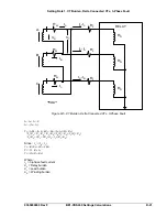
Step 3.
types
Step 4. Calculate
to
TAP3
and
TAP1
to
TAP3
. If
greater
ratios to bring the tap ratios to less than 10
winding relative to the main winding,
this typically will
the lower rated winding to reduce the CT's normal
Step 5 If tap ratios are less than 10, but one of the taps is beyond the range of 2 to 20, the taps may be
s a whole linearly in a direction that maintains the original tap ratios but brings all taps
to within acceptable limits. For instance, if
TAP3
had been calculated to some value above 20,
sensitivity of the relay. In non-numerical relays
.g., Basler Electric BE1-87T), the minpu was fixed at a typical value of 0.35 of the relay tap. In the BE1-
DS240 relay, the user can choose lower or higher values to optimize the protection in each particular
pplication. Selecting a lower minpu setting will tend to raise the slope setting needed to maintain a given
haracteristic. (For more information, see the
Calculate
lope
later in this section.) Conversely, it is sometimes necessary to accommodate unmonitored loads in
the differential zone. In that case, the minpu setting may be higher. A setting of
0.25
per unit of
transfor
If the calculated TAP1, TAP2 and TAP3 are in range (2.00 - 20.0 for 5 ampere sensing input
or 0.40 - 4.00 for 1 ampere sensing input types) proceed to Calculate Minpu. If they are not in
range, proceed with Step 4.
spread ratio. Determine the ratio of
TAP1
to
TAP2
,
TAP2
than 10:1 (or conversely, 1:10), adjust the CT
(or greater than 0.1). In transformers with a lower
MVA
rated
mean raising the CT ratio of
current under full load conditions to a fairly low level.
adjusted a
then reset
TAP3
to 20 and reset
TAP1
and
TAP2
to a lower value using the equation:
Calculate Minpu
The minimum pickup restraint setting (minpu) adjusts the
3
TAP
Old
20
2
TAP
Old
2
TAP
New
3
TAP
Old
20
1
TAP
Old
1
TAP
New
(e
C
a
margin at the knee-point of the differential tripping c
S
mer full load (
FA
) rating
(i,e., top MVA) is recommended for typical installations whe
ored load needs to be considered. This value is well above the magnetizing current and pr
argin at the knee point of the slope characteristic. If un
re no
unmonit
ovides
a safe m
monitored loads such as station service or
small capacitor banks are connected in the differential zone, the minpu must be increased by the
magnitude of the unmonitored current in multiples of tap.
Summary of Contents for BE1-CDS240
Page 2: ......
Page 8: ...vi BE1 CDS240 Introduction 9365200990 Rev F This page intentionally left blank ...
Page 38: ...1 28 BE1 CDS240 General Information 9365200990 Rev F This page intentionally left blank ...
Page 40: ...ii BE1 CDS240 Quick Start 9365200990 Rev F This page intentionally left blank ...
Page 152: ...ii BE1 CDS240 Metering 9365200990 Rev F This page intentionally left blank ...
Page 226: ...iv BE1 CDS240 Application 9365200990 Rev F This page intentionally left blank ...
Page 286: ...ii BE1 CDS240 Security 9365200990 Rev F This page intentionally left blank ...
Page 290: ...9 4 BE1 CDS240 Security 9365200990 Rev F This page intentionally left blank ...
Page 292: ...ii BE1 CDS240 Human Machine Interface 9365200990 Rev F This page intentionally left blank ...
Page 306: ...10 14 BE1 CDS240 Human Machine Interface 9365200990 Rev F This page intentionally left blank ...
Page 308: ...ii BE1 CDS240 ASCII Command Interface 9365200990 Rev F This page intentionally left blank ...
Page 342: ...11 34 BE1 CDS240 ASCII Command Interface 9365200990 Rev F This page intentionally left blank ...
Page 349: ...Figure 12 5 Horizontal Rack Mount Front View 9365200990 Rev F BE1 CDS240 Installation 12 5 ...
Page 361: ...Figure 12 17 Typical DC Connection Diagrams 9365200990 Rev F BE1 CDS240 Installation 12 17 ...
Page 372: ...12 28 BE1 CDS240 Installation 9365200990 Rev F This page intentionally left blank ...
Page 468: ...13 92 BE1 CDS240 Testing and Maintenance 9365200990 Rev F This page intentionally left blank ...
Page 512: ...14 42 BE1 CDS240 BESTCOMS Software 9365200990 Rev F This page intentionally left blank ...
Page 544: ...ii BE1 CDS240 Terminal Communication 9365200990 Rev F This page intentionally left blank ...
Page 550: ...ii BE1 CDS240 Settings Calculations 9365200990 Rev F This page intentionally left blank ...
Page 578: ...D 28 BE1 CDS240 Settings Calculations 9365200990 Rev F This page intentionally left blank ...
Page 579: ......