


In applications where the time coordination between curves is extremely close, we recommend that you
choose the optimal time dial setting by inspection of the coordination study. In applications where
coordination is tight, it is recommended that you retrofit your circuits with Basler Electric electronic relays
to ensure high timing accuracy.
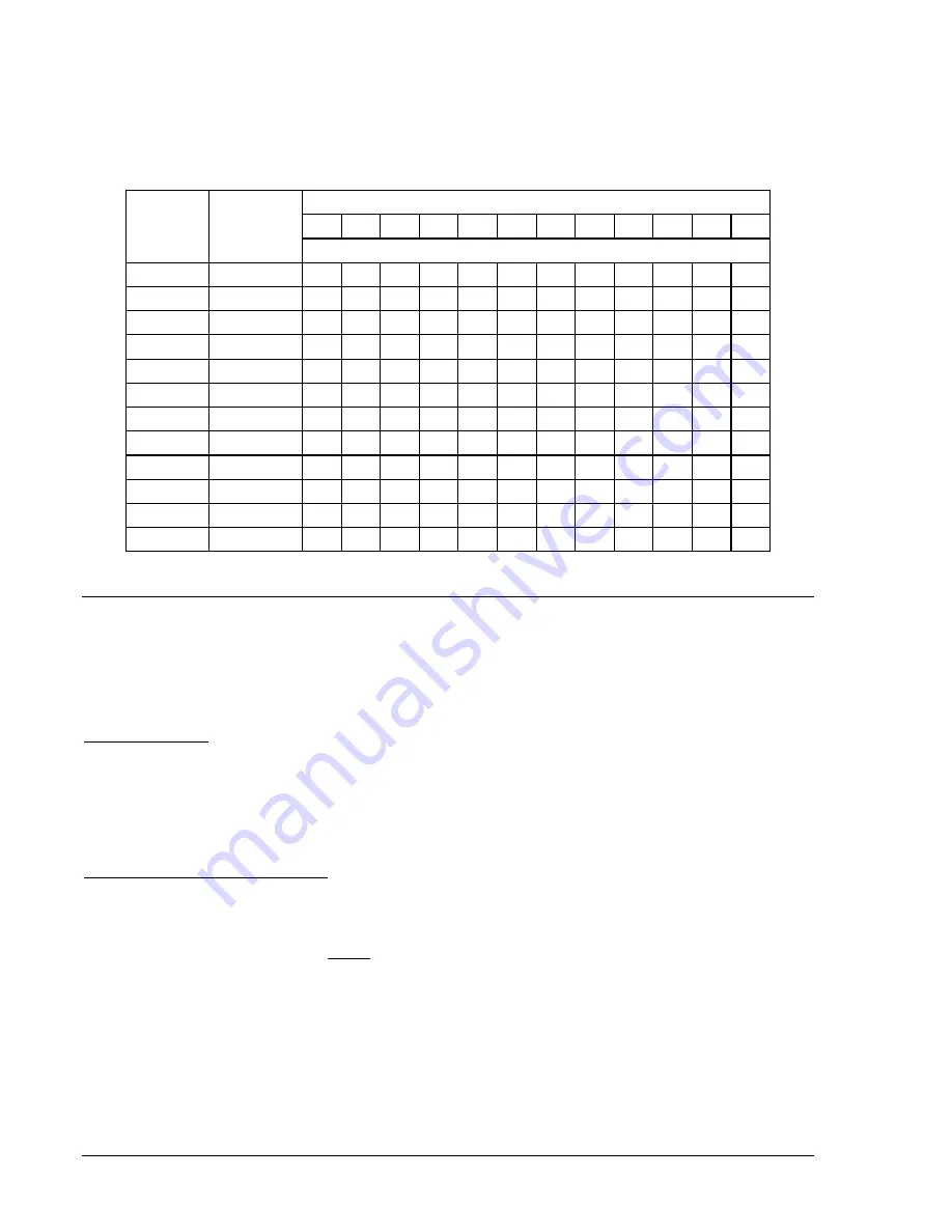
Table A-3. Time Dial Setting Cross-Reference
Electromechanical Relay Time Dial Setting
0.5 1.0 2.0 3.0 4.0 5.0 6.0 7.0 8.0 9.0 10.0
11.0
Curve
Equivalent
To
Basler Electric Equivalent Time Dial Setting
S, S1
ABB
CO-2 0.3 0.8 1.7 2.4 3.4 4.2 5.0 5.8 6.7 7.7 8.6 9.7
L, L1
ABB
CO-5 0.4 0.8 1.5 2.3 3.3 4.2 5.0 6.0 7.0 7.8 8.8 9.9
D
ABB
CO-6 0.5 1.1 2.0 2.9 3.7 4.5 5.0 5.9 7.2 8.0 8.9 10.1
M
ABB
CO-7 0.4 0.8 1.7 2.5 3.3 4.3 5.3 6.1 7.0 8.0 9.0 9.8
I, I1
ABB
CO-8 0.3 0.7 1.5 2.3 3.2 4.0 5.0 5.8 6.8 7.6 8.7 10.0
V, V1
ABB
CO-9 0.3 0.7 1.4 2.1 3.0 3.9 4.8 5.7 6.7 7.8 8.7 9.6
E, E1
ABB
CO-11 0.3 0.7 1.5 2.4 3.2 4.2 5.0 5.7 6.6 7.8 8.5 10.3
I2
GE
IAC-51 0.6 1.0 1.9 2.7 3.7 4.8 5.7 6.8 8.0 9.3 10.6 N/A
V2
GE
IAC-53 0.4 0.8 1.6 2.4 3.4 4.3 5.1 6.3 7.2 8.4 9.6 N/A
S2
GE
IAC-55 0.2 1.0 2.0 3.1 4.0 4.9 6.1 7.2 8.1 8.9 9.8 N/A
L2
GE
IAC-66 0.4 0.9 1.8 2.7 3.9 4.9 6.3 7.2 8.5 9.7 10.9 N/A
E2
GE
IAC-77 0.5 1.0 1.9 2.7 3.5 4.3 5.2 6.2 7.4 8.2 9.9 N/A
THE 46 CURVE
The 46 curve (Figure A-17) is a special curve designed to emulate the (I
2
)
2
t withstand ratings of
generators using what is frequently referred to as the generator K factor.
The 46 Curve Characteristics
46 Pickup Current
Generators have a maximum continuous rating for negative sequence current. This is typically expressed
as a percent of stator rating. When using the 46 curve, the user should convert the continuous I
2
rating
data to actual secondary current at the relay. This value (plus some margin, if appropriate) should be
entered as the pickup setting. For example, if a generator’s rated full-load current is 5 amperes, a pu
setting of 0.5 A would allow 10% continuous I
2
.
46 Time Dial (= Generator K factor)
The amount of time that a generator can withstand a given level of unbalance is defined by Equation A-3.
2
2
I
K
t
Equation A-3
The K factor gives the time that a generator can withstand 1 per unit negative sequence current. For
example, with a K factor of 20, since (I
2
)
2
becomes 1 at 1 per unit of current, the generator can withstand
the condition for 20 seconds. Typical values for generator K factors are in the 2 to 40 range. The relay
uses the “nominal current” setting of the relay (via BESTCOMS or the SG-NOM command) to determine
what corresponds to 1 per unit current in the generator.
A-4
BE1-CDS240 Time Overcurrent Characteristic Curves
9365200990 Rev F
Summary of Contents for BE1-CDS240
Page 2: ......
Page 8: ...vi BE1 CDS240 Introduction 9365200990 Rev F This page intentionally left blank ...
Page 38: ...1 28 BE1 CDS240 General Information 9365200990 Rev F This page intentionally left blank ...
Page 40: ...ii BE1 CDS240 Quick Start 9365200990 Rev F This page intentionally left blank ...
Page 152: ...ii BE1 CDS240 Metering 9365200990 Rev F This page intentionally left blank ...
Page 226: ...iv BE1 CDS240 Application 9365200990 Rev F This page intentionally left blank ...
Page 286: ...ii BE1 CDS240 Security 9365200990 Rev F This page intentionally left blank ...
Page 290: ...9 4 BE1 CDS240 Security 9365200990 Rev F This page intentionally left blank ...
Page 292: ...ii BE1 CDS240 Human Machine Interface 9365200990 Rev F This page intentionally left blank ...
Page 306: ...10 14 BE1 CDS240 Human Machine Interface 9365200990 Rev F This page intentionally left blank ...
Page 308: ...ii BE1 CDS240 ASCII Command Interface 9365200990 Rev F This page intentionally left blank ...
Page 342: ...11 34 BE1 CDS240 ASCII Command Interface 9365200990 Rev F This page intentionally left blank ...
Page 349: ...Figure 12 5 Horizontal Rack Mount Front View 9365200990 Rev F BE1 CDS240 Installation 12 5 ...
Page 361: ...Figure 12 17 Typical DC Connection Diagrams 9365200990 Rev F BE1 CDS240 Installation 12 17 ...
Page 372: ...12 28 BE1 CDS240 Installation 9365200990 Rev F This page intentionally left blank ...
Page 468: ...13 92 BE1 CDS240 Testing and Maintenance 9365200990 Rev F This page intentionally left blank ...
Page 512: ...14 42 BE1 CDS240 BESTCOMS Software 9365200990 Rev F This page intentionally left blank ...
Page 544: ...ii BE1 CDS240 Terminal Communication 9365200990 Rev F This page intentionally left blank ...
Page 550: ...ii BE1 CDS240 Settings Calculations 9365200990 Rev F This page intentionally left blank ...
Page 578: ...D 28 BE1 CDS240 Settings Calculations 9365200990 Rev F This page intentionally left blank ...
Page 579: ......