


9365200990 Rev F
BE1-CDS240 Quick Start
2-3
Element Logic Settings
To use a protection or control element, two items need to be set. These are the mode and the input logic.
The mode is equivalent to deciding which devices you want to install in your protection and control
scheme. You then must set the logic variables that will be connected to the inputs.
For example, the 51N element has two modes (disabled and enabled), and one input, block (torque
control). To use this element, the logic setting command might be SL-51N=1,/IN2 for Set Logic-51N to be
Mode 1 (enabled) with the element blocked when contact sensing Input 2 is not (/) energized. Contact
Sensing Input 2 would be wired to a ground relay enable switch.
As noted before, the protection settings for this element, pickup, time dial, and curve, must be set
separately in the setting group settings. The setting might be S0-51N=6.5,2.1,S1R for Set in Setting
Group 0 - the 51N function = to pickup at 6.5 amps with a time dial of 2.1 using curve S1 with an
integrating reset characteristic.
The 51N element has two logic output variables, 51NT (Trip) and 51NPU (Picked Up). The combination of
the logic settings and the operational settings for the element govern how these variables respond to logic
and current inputs.
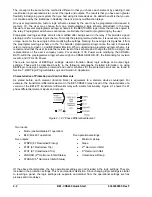
Output Logic Settings
BESTlogic, as implemented in the BE1-CDS240, supports up to 16 output expressions. The output
expressions are called virtual outputs to distinguish them from the physical output relays. In the BE1-
CDS240, any virtual output (VO1 through VO16) can drive any physical output relay (OUT1 through
OUT14). VOA is different in that it will always drives physical output relay, Out A which is the fail safe
alarm output. Other virtual outputs may be assigned to or removed from OUTA, but VOA will always drive
OUTA. In addition, any of the virtual outputs can be used for intermediate logic expressions.
For example, OUT1 is wired to the trip bus of a circuit breaker. To set up the logic to trip the breaker, the
BESTlogic setting command might be SL-VO1=VO11+101T+BFPU for Set Logic - Virtual Output 1 = to
Virtual Output 11 (which is the intermediate logic expression for all of the element tripping outputs) or (+)
101T (the trip output of the virtual breaker control switch) or (+) BFPU (the pickup output of the breaker
failure element that indicates that breaker failure has been initiated). To assign this to OUT1, the
BESTlogic command would be SL-OUT1=VO1.
USER INTERFACES
Three user interfaces are provided for interacting with the BE1-CDS240 relay: the front panel HMI, ASCII
communications, and the BESTCOMS for BE1-CDS240 software. The front panel HMI provides access to
a subset of the total functionality of the device. ASCII communications provides access to all settings,
controls, reports, and metering functionality of the system. The BESTCOMS for BE1-CDS240 software
provides a Windows based, user-friendly environment for editing settings files and uploading and
downloading them from the relay (see Section 14 for details).
Front Panel HMI
The front panel HMI consists of a two line by a 16 character LCD (liquid crystal display) with four scrolling
pushbuttons, an edit pushbutton, and a reset pushbutton. The
EDIT
pushbutton includes an LED to
indicate when edit mode is active. There are five other LEDs for indicating power supply status, relay
trouble alarm status, programmable major and minor alarm status, and a multipurpose
Trip
LED that
flashes to indicate that a protective element is picked up. The
Trip
LED lights continuously when the trip
output is energized and seals in when a protective trip has occurred to indicate that target information is
being displayed on the LCD. A complete description of the HMI is included in Section 10,
Human-
Machine Interface
.
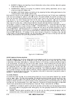
The BE1-CDS240 HMI is menu driven and organized into a menu tree structure with six branches. A
complete menu tree description with displays is also provided in Section 10,
Human-Machine Interface
. A
list of the menu branches and a brief description for scrolling through the menu is in the following
paragraphs.
1. REPORT STATUS. Display and resetting of general status information such as targets, alarms,
recloser status, etc.
2. CONTROL. Operation of manual controls such as virtual switches, selection of active setting
group, etc.
3. METERING. Display of real time metering values.
Summary of Contents for BE1-CDS240
Page 2: ......
Page 8: ...vi BE1 CDS240 Introduction 9365200990 Rev F This page intentionally left blank ...
Page 38: ...1 28 BE1 CDS240 General Information 9365200990 Rev F This page intentionally left blank ...
Page 40: ...ii BE1 CDS240 Quick Start 9365200990 Rev F This page intentionally left blank ...
Page 152: ...ii BE1 CDS240 Metering 9365200990 Rev F This page intentionally left blank ...
Page 226: ...iv BE1 CDS240 Application 9365200990 Rev F This page intentionally left blank ...
Page 286: ...ii BE1 CDS240 Security 9365200990 Rev F This page intentionally left blank ...
Page 290: ...9 4 BE1 CDS240 Security 9365200990 Rev F This page intentionally left blank ...
Page 292: ...ii BE1 CDS240 Human Machine Interface 9365200990 Rev F This page intentionally left blank ...
Page 306: ...10 14 BE1 CDS240 Human Machine Interface 9365200990 Rev F This page intentionally left blank ...
Page 308: ...ii BE1 CDS240 ASCII Command Interface 9365200990 Rev F This page intentionally left blank ...
Page 342: ...11 34 BE1 CDS240 ASCII Command Interface 9365200990 Rev F This page intentionally left blank ...
Page 349: ...Figure 12 5 Horizontal Rack Mount Front View 9365200990 Rev F BE1 CDS240 Installation 12 5 ...
Page 361: ...Figure 12 17 Typical DC Connection Diagrams 9365200990 Rev F BE1 CDS240 Installation 12 17 ...
Page 372: ...12 28 BE1 CDS240 Installation 9365200990 Rev F This page intentionally left blank ...
Page 468: ...13 92 BE1 CDS240 Testing and Maintenance 9365200990 Rev F This page intentionally left blank ...
Page 512: ...14 42 BE1 CDS240 BESTCOMS Software 9365200990 Rev F This page intentionally left blank ...
Page 544: ...ii BE1 CDS240 Terminal Communication 9365200990 Rev F This page intentionally left blank ...
Page 550: ...ii BE1 CDS240 Settings Calculations 9365200990 Rev F This page intentionally left blank ...
Page 578: ...D 28 BE1 CDS240 Settings Calculations 9365200990 Rev F This page intentionally left blank ...
Page 579: ......