


Locator Description
G
Communication Port 0
– This RS-232 serial port can be used to communicate with the relay
using simple ASCII command language. A computer terminal or PC running terminal
emulation software (such as Windows
HyperTerminal) is required to send commands to
the relay or receive information from the relay.
H
Reset Pushbutton
– Pushing this switch will reset the Trip LED, sealed-in Trip Targets, Peak
Demand Currents, and Alarms.
I
Scrolling Pushbuttons
– Use these four switches to navigate
(UP/DOWN/LEFT/RIGHT)
through the LCD’s menu tree. When in Edit mode, the
LEFT
and
RIGHT
scrolling
pushbuttons select the variable to be changed. The
UP
and
DOWN
scrolling pushbuttons
change the variable.
J
Edit Pushbutton
– Settings changes can be made at the front panel using this switch. When
pushed, this switch lights to indicate that Edit mode is active. When you are finished making
settings changes (using the scrolling pushbuttons) and the
Edit
switch is pressed again, the
switch light turns off to indicate that your settings changes have been saved. If changes
aren’t completed and saved within five minutes, the relay will automatically exit the Edit
mode without saving any changes.
K
Display
– 64 by 128 pixel graphic liquid crystal display (LCD) with backlighting. The LCD is
the primary source for obtaining information from the relay or when locally setting the relay.
Information such as targets, metering values, demand values, communication parameters,
the active logic scheme name, and diagnostic information is provided by the LCD.
Information and settings are displayed in a menu with branches. The
Menu Tree
subsection
provides more information about the menu branches.
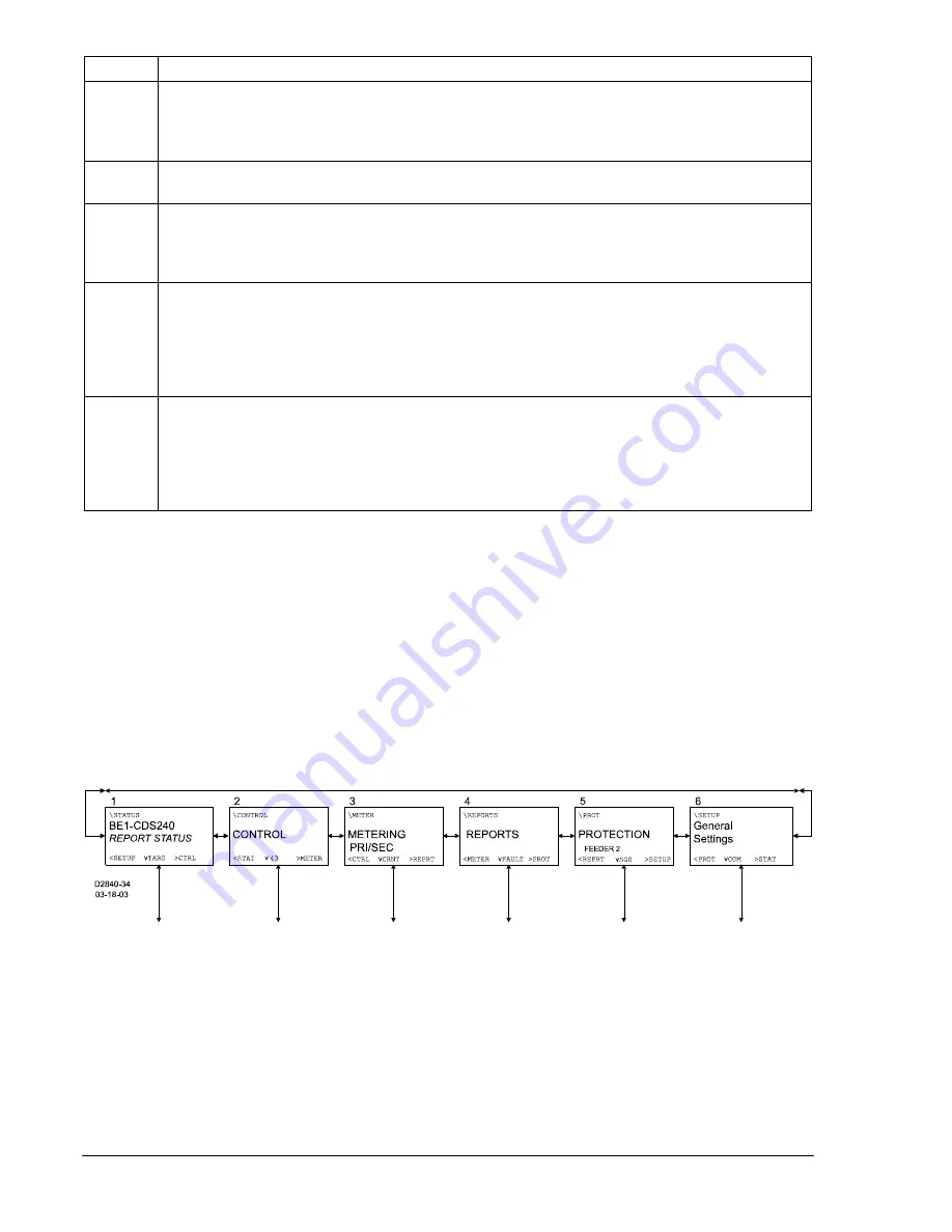
Menu Tree
A menu tree with six branches can be accessed through the front panel controls and display. The
LEFT
and
RIGHT
scrolling pushbuttons are used to view each of the six branches. A greater level of detail in a
menu branch is accessed using the
DOWN
scrolling pushbutton. The branch path is located in the upper
left hand corner. This path is like a computer file path and indicates the current branch and level in the
menu tree structure. This path helps so that you do not loose track of where you are in the menu tree.
Each time you go to a lower level in the menu tree, another branch is added to the screen path and is
separated by a backslash. The
UP
scrolling pushbutton is used to return to the top of the menu branch.
The six branches of the menu tree are illustrated in Figure 10-2 and summarized in the following
paragraphs.
Figure 10-2. BE1-CDS240 Menu Tree (Top Level, All Branches)
1. REPORT STATUS – Provides display and resetting of general status information such as targets,
alarms, and recloser status. Figure 10-3 illustrates the structure of the Report Status menu
branch.
2. CONTROL – Accesses control function operation of virtual switches, active setting group
selection, and others. Control menu branch structure is illustrated in Figure 10-4.
3. METERING – Displays real time metering values. Figure 10-5 illustrates the structure of the
Metering menu branch.
10-2
BE1-CDS240 Human-Machine Interface
9365200990 Rev F
Summary of Contents for BE1-CDS240
Page 2: ......
Page 8: ...vi BE1 CDS240 Introduction 9365200990 Rev F This page intentionally left blank ...
Page 38: ...1 28 BE1 CDS240 General Information 9365200990 Rev F This page intentionally left blank ...
Page 40: ...ii BE1 CDS240 Quick Start 9365200990 Rev F This page intentionally left blank ...
Page 152: ...ii BE1 CDS240 Metering 9365200990 Rev F This page intentionally left blank ...
Page 226: ...iv BE1 CDS240 Application 9365200990 Rev F This page intentionally left blank ...
Page 286: ...ii BE1 CDS240 Security 9365200990 Rev F This page intentionally left blank ...
Page 290: ...9 4 BE1 CDS240 Security 9365200990 Rev F This page intentionally left blank ...
Page 292: ...ii BE1 CDS240 Human Machine Interface 9365200990 Rev F This page intentionally left blank ...
Page 306: ...10 14 BE1 CDS240 Human Machine Interface 9365200990 Rev F This page intentionally left blank ...
Page 308: ...ii BE1 CDS240 ASCII Command Interface 9365200990 Rev F This page intentionally left blank ...
Page 342: ...11 34 BE1 CDS240 ASCII Command Interface 9365200990 Rev F This page intentionally left blank ...
Page 349: ...Figure 12 5 Horizontal Rack Mount Front View 9365200990 Rev F BE1 CDS240 Installation 12 5 ...
Page 361: ...Figure 12 17 Typical DC Connection Diagrams 9365200990 Rev F BE1 CDS240 Installation 12 17 ...
Page 372: ...12 28 BE1 CDS240 Installation 9365200990 Rev F This page intentionally left blank ...
Page 468: ...13 92 BE1 CDS240 Testing and Maintenance 9365200990 Rev F This page intentionally left blank ...
Page 512: ...14 42 BE1 CDS240 BESTCOMS Software 9365200990 Rev F This page intentionally left blank ...
Page 544: ...ii BE1 CDS240 Terminal Communication 9365200990 Rev F This page intentionally left blank ...
Page 550: ...ii BE1 CDS240 Settings Calculations 9365200990 Rev F This page intentionally left blank ...
Page 578: ...D 28 BE1 CDS240 Settings Calculations 9365200990 Rev F This page intentionally left blank ...
Page 579: ......


