


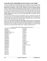


Alarms
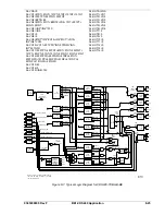
Three logic variables drive the front panel LEDs: Relay Trouble (ALMREL), Major Alarm (ALMMAJ), and
Minor Alarm (ALMMIN). A fourth logic variable, Logic Alarm (ALMLGC), has no associated front panel
LED. When the relay self-test detects a problem in the relay (ALMREL) as programmed for the CDS240-
TXBU-A-BE scheme, the Relay Trouble LED lights, output A operates and all outputs are disabled. When
a Major Alarm is detected (ALMMAJ), the associated LED lights, but in this scheme, no output relay is
programmed to operate. When a Minor Alarm (ALMMIN) is detected, the associated LED lights, but in this
scheme, no output relay is programmed to operate.
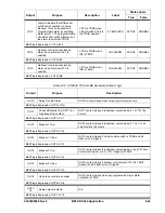
Table 8-20. CDS240-TXBU-B-BE Contact Input Logic
State Labels
Input Purpose Name
Label
Energized De-Energized
IN1
Optional input. Used for CT input circuit 1 breaker
status indication in SER reports. TRUE when
breaker is closed.
BREAKER-1 CLOSED
OPEN
IN2
Optional input. Used for CT input circuit 2 breaker
status indication in SER reports. TRUE when
breaker is closed.
BREAKER-2 CLOSED
OPEN
IN3
Optional input. Used for 86T status indication and
locks out the low-side and high-side breakers
when TRUE. TRUE when 86T is tripped.
86T-TRIPPED TRIPPED
NORMAL
IN4
Optional Input. Used for 86B status indication and
locks out the low-side breaker when TRUE.
TRUE when 86B is tripped.
86B-TRIPPED TRIPPED
NORMAL
IN5
Puts transformer and bus relays in feeder backup
mode when feeder relay out-of-service is
detected by an open contact. Feeder relays such
as BE1-851 or BE1-951 using one of the
preprogrammed schemes with interlock logic.
FEEDERS_OK NORMAL
FDR_OOS
IN6
Breaker Failure Initiate by external relays with
breaker status supervision. Typically used for
differential or sudden pressure tripping.
EXT-BFI-52B-
SUPV
INI NORMAL
NOTE
Tables 8-20 through 8-24 provide detailed logic definitions for the inputs, outputs,
protection, and control elements. Only those inputs, logic blocks, virtual switches,
and outputs in use for the CDS240-TXBU-B-BE preprogrammed logic are
described in the following tables.
CAUTION
Test Mode Enable does not defeat the trip outputs of the relay. External trip test
blades must be opened or the CDS240-TXBU-B-BE logic scheme must be
modified to suit the user's test mode requirements. One option is to trip the
breakers through an 86 device only. Typically, 86 devices are installed with test
blades in the breaker trip circuit so that the protection scheme can be safely
operational checked while the primary equipment is in service. Another option is
to inhibit all trip outputs when test mode is enabled. However, external devices
such as auxiliary relays and 86 devices would no longer be included in the
operational test.
9365200990 Rev F
BE1-CDS240 Application
8-29
Summary of Contents for BE1-CDS240
Page 2: ......
Page 8: ...vi BE1 CDS240 Introduction 9365200990 Rev F This page intentionally left blank ...
Page 38: ...1 28 BE1 CDS240 General Information 9365200990 Rev F This page intentionally left blank ...
Page 40: ...ii BE1 CDS240 Quick Start 9365200990 Rev F This page intentionally left blank ...
Page 152: ...ii BE1 CDS240 Metering 9365200990 Rev F This page intentionally left blank ...
Page 226: ...iv BE1 CDS240 Application 9365200990 Rev F This page intentionally left blank ...
Page 286: ...ii BE1 CDS240 Security 9365200990 Rev F This page intentionally left blank ...
Page 290: ...9 4 BE1 CDS240 Security 9365200990 Rev F This page intentionally left blank ...
Page 292: ...ii BE1 CDS240 Human Machine Interface 9365200990 Rev F This page intentionally left blank ...
Page 306: ...10 14 BE1 CDS240 Human Machine Interface 9365200990 Rev F This page intentionally left blank ...
Page 308: ...ii BE1 CDS240 ASCII Command Interface 9365200990 Rev F This page intentionally left blank ...
Page 342: ...11 34 BE1 CDS240 ASCII Command Interface 9365200990 Rev F This page intentionally left blank ...
Page 349: ...Figure 12 5 Horizontal Rack Mount Front View 9365200990 Rev F BE1 CDS240 Installation 12 5 ...
Page 361: ...Figure 12 17 Typical DC Connection Diagrams 9365200990 Rev F BE1 CDS240 Installation 12 17 ...
Page 372: ...12 28 BE1 CDS240 Installation 9365200990 Rev F This page intentionally left blank ...
Page 468: ...13 92 BE1 CDS240 Testing and Maintenance 9365200990 Rev F This page intentionally left blank ...
Page 512: ...14 42 BE1 CDS240 BESTCOMS Software 9365200990 Rev F This page intentionally left blank ...
Page 544: ...ii BE1 CDS240 Terminal Communication 9365200990 Rev F This page intentionally left blank ...
Page 550: ...ii BE1 CDS240 Settings Calculations 9365200990 Rev F This page intentionally left blank ...
Page 578: ...D 28 BE1 CDS240 Settings Calculations 9365200990 Rev F This page intentionally left blank ...
Page 579: ......