


Table 4-35. 60FL Element Blocking Settings
Mode
Input
Setting Explanation Default
DIS
When
I
Block is disabled, current tripping level is determined by the
sensing voltage level (51/27R operates normally).
I Block
ENA
When
I
Block is enabled and the 60FL logic is TRUE (voltage sensing is
lost), the current tripping level is controlled by the 51P function and the
27R function is inhibited. When
I
Block is enabled and the 60FL logic is
FALSE, the current tripping level is controlled by the 51/27R function.
ENA
DIS
Phase (P), Neutral (N), and Negative-Sequence (Q) voltage functions are
not automatically blocked when 60FL logic is TRUE.
P
All functions that use phase voltage are blocked when the 60FL logic is
TRUE. (27P/127P and 59P/159P)
N
All functions that use 3-phase residual voltage (3V
0
) measurements are
blocked when the 60FL logic is TRUE. (59X - Mode 2)
V
Block
Q
All functions that use the negative-sequence voltage (V
2
) measurement
are blocked when the 60FL logic is TRUE. (47)
PNQ
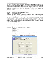
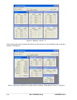
Figure 4-63. Reporting and Alarms Screen, VT Monitor Tab
The directional tests are also supervised by the loss of potential function 60FL. If the 60FL bit is TRUE,
then voltage sensing was loss or is unreliable. Under this condition positive, negative, and zero-sequence
directional tests are disabled and their bits are cleared. There is no user setting to enable or disabled this
supervision. Current polarization is not effected by the 60FL since it does not rely on voltage sensing.
Similarly, zero-sequence voltage polarization can only be performed if 3P4W sensing is selected. The
following qualifiers are applied to the voltage polarized ground direction element based on the user
selected input quantity:
4-66
BE1-CDS240 Protection and Control
9365200990 Rev F
Summary of Contents for BE1-CDS240
Page 2: ......
Page 8: ...vi BE1 CDS240 Introduction 9365200990 Rev F This page intentionally left blank ...
Page 38: ...1 28 BE1 CDS240 General Information 9365200990 Rev F This page intentionally left blank ...
Page 40: ...ii BE1 CDS240 Quick Start 9365200990 Rev F This page intentionally left blank ...
Page 152: ...ii BE1 CDS240 Metering 9365200990 Rev F This page intentionally left blank ...
Page 226: ...iv BE1 CDS240 Application 9365200990 Rev F This page intentionally left blank ...
Page 286: ...ii BE1 CDS240 Security 9365200990 Rev F This page intentionally left blank ...
Page 290: ...9 4 BE1 CDS240 Security 9365200990 Rev F This page intentionally left blank ...
Page 292: ...ii BE1 CDS240 Human Machine Interface 9365200990 Rev F This page intentionally left blank ...
Page 306: ...10 14 BE1 CDS240 Human Machine Interface 9365200990 Rev F This page intentionally left blank ...
Page 308: ...ii BE1 CDS240 ASCII Command Interface 9365200990 Rev F This page intentionally left blank ...
Page 342: ...11 34 BE1 CDS240 ASCII Command Interface 9365200990 Rev F This page intentionally left blank ...
Page 349: ...Figure 12 5 Horizontal Rack Mount Front View 9365200990 Rev F BE1 CDS240 Installation 12 5 ...
Page 361: ...Figure 12 17 Typical DC Connection Diagrams 9365200990 Rev F BE1 CDS240 Installation 12 17 ...
Page 372: ...12 28 BE1 CDS240 Installation 9365200990 Rev F This page intentionally left blank ...
Page 468: ...13 92 BE1 CDS240 Testing and Maintenance 9365200990 Rev F This page intentionally left blank ...
Page 512: ...14 42 BE1 CDS240 BESTCOMS Software 9365200990 Rev F This page intentionally left blank ...
Page 544: ...ii BE1 CDS240 Terminal Communication 9365200990 Rev F This page intentionally left blank ...
Page 550: ...ii BE1 CDS240 Settings Calculations 9365200990 Rev F This page intentionally left blank ...
Page 578: ...D 28 BE1 CDS240 Settings Calculations 9365200990 Rev F This page intentionally left blank ...
Page 579: ......


