


Example 1.
Make the following settings to the 62 Logic Timer. Figure 4-59 illustrates these settings.
Logic:
User
Mode:
One Shot Non-Retriggerable
INITIATE:
IN2
BLOCK:
0
Operating Settings for General Purpose Logic Timers
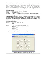
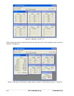
Operating settings are made using BESTCOMS. Figure 4-60 illustrates the BESTCOMS screen used to
select operational settings for the Logic Timer elements. To open the
Logic Timers
screen, select
Logic
Timers
from the
Screens
pull-down menu. Alternately, settings may be made using the S<g>-x62 ASCII
command or through the optional HMI interface using Screen 5.#.9.1, \PROT\SG#\62\SETTINGS.
Figure 4-60. Logic Timers Screen
At the top left of the screen is a pull-down menu labeled
Logic
. This menu allows viewing of the
BESTlogic settings for each preprogrammed logic scheme. User or custom logic
must
be selected on this
menu in order to allow changes to be made to the mode and inputs of the element.
Beneath the
Logic
pull-down menu is a pull-down menu labeled
Settings
. The Settings menu is used to
select the setting group that the element's settings apply to. See Section 7,
BESTlogic Programmable
Logic, Logic Schemes
.
Using the pull-down menus and buttons, make the application appropriate settings to the Logic Timer
elements.
Table 4-33 summarizes the operating settings for General Purpose Logic Timers.
Table 4-33. Operating Settings for General Purpose Logic Timers
Setting
Range
Increment
Unit of Measure
Default
0 to 999 ms
1
Milliseconds
0.1 for 0.1 to 9.9 sec.
0.1 to 9999 sec.
1.0 for 10 to 9999 sec.
Seconds
T1 Time,
T2 Time
0 to 599,940 (60 Hz)
0 to 499,950 (50Hz)
Cycles
0
9365200990 Rev F
BE1-CDS240 Protection and Control
4-63
Summary of Contents for BE1-CDS240
Page 2: ......
Page 8: ...vi BE1 CDS240 Introduction 9365200990 Rev F This page intentionally left blank ...
Page 38: ...1 28 BE1 CDS240 General Information 9365200990 Rev F This page intentionally left blank ...
Page 40: ...ii BE1 CDS240 Quick Start 9365200990 Rev F This page intentionally left blank ...
Page 152: ...ii BE1 CDS240 Metering 9365200990 Rev F This page intentionally left blank ...
Page 226: ...iv BE1 CDS240 Application 9365200990 Rev F This page intentionally left blank ...
Page 286: ...ii BE1 CDS240 Security 9365200990 Rev F This page intentionally left blank ...
Page 290: ...9 4 BE1 CDS240 Security 9365200990 Rev F This page intentionally left blank ...
Page 292: ...ii BE1 CDS240 Human Machine Interface 9365200990 Rev F This page intentionally left blank ...
Page 306: ...10 14 BE1 CDS240 Human Machine Interface 9365200990 Rev F This page intentionally left blank ...
Page 308: ...ii BE1 CDS240 ASCII Command Interface 9365200990 Rev F This page intentionally left blank ...
Page 342: ...11 34 BE1 CDS240 ASCII Command Interface 9365200990 Rev F This page intentionally left blank ...
Page 349: ...Figure 12 5 Horizontal Rack Mount Front View 9365200990 Rev F BE1 CDS240 Installation 12 5 ...
Page 361: ...Figure 12 17 Typical DC Connection Diagrams 9365200990 Rev F BE1 CDS240 Installation 12 17 ...
Page 372: ...12 28 BE1 CDS240 Installation 9365200990 Rev F This page intentionally left blank ...
Page 468: ...13 92 BE1 CDS240 Testing and Maintenance 9365200990 Rev F This page intentionally left blank ...
Page 512: ...14 42 BE1 CDS240 BESTCOMS Software 9365200990 Rev F This page intentionally left blank ...
Page 544: ...ii BE1 CDS240 Terminal Communication 9365200990 Rev F This page intentionally left blank ...
Page 550: ...ii BE1 CDS240 Settings Calculations 9365200990 Rev F This page intentionally left blank ...
Page 578: ...D 28 BE1 CDS240 Settings Calculations 9365200990 Rev F This page intentionally left blank ...
Page 579: ......


