


9170700990 Rev D
BE1-60 Installation
4-1
SECTION 4
•
INSTALLATION
INTRODUCTION
BE1-60 relays are shipped in sturdy cartons to prevent damage during transit. Upon receipt of a relay,
check the model and style number against the requisition and packing list to see that they agree. Inspect
the relay for shipping damage. If there is evidence of damage, file a claim with the carrier, and notify the
regional sales office or Basler Electric.
If the relay will not be installed immediately, place the relay in its original shipping carton and store in a
moisture- and dust-free environment.
RELAY OPERATING GUIDELINES AND PRECAUTIONS
Before installing or operating the relay, not the following guidelines and precautions.
•
For proper current operated target operation, a minimum current of 200 milliamperes must flow
through the output trip circuit.
•
If a wiring insulation test is required, remove the connection plugs and withdraw the relay from its
case.
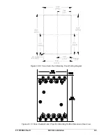
MOUNTING
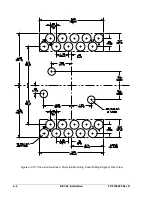
Because the relay is of solid-state design, it may be mounted at any convenient angle. Relay case
dimension drawings and panel cutting and drilling diagrams are provided in Figures 4-1 through 4-6.
CAUTION
When the connection plugs are removed, the relay is disconnected from the
operating circuit and will not provide system protection. Always be sure that
external operating (monitored) conditions are stable before removing a relay for
inspection, test, or service.
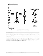
NOTE
Be sure that the relay is hard-wired to earth ground with no smaller than 12 AWG
copper wire attached to the ground terminal on the rear of the case. When the
relay is configured in a system with other devices, it is recommended to use a
separate lead to the ground bus from each device.
Summary of Contents for BE1-60
Page 1: ...INSTRUCTION MANUAL FOR VOLTAGE BALANCE RELAY BE1 60 Publication 9170700990 Revision D 09 07...
Page 2: ......
Page 6: ...iv BE1 60 Introduction 9170700990 Rev D This page intentionally left blank...
Page 8: ...vi BE1 60 Introduction 9170700990 Rev D This page intentionally left blank...
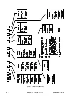
Page 12: ...1 4 BE1 60 General Information 9170700990 Rev D Figure 1 3 BE1 60 Style Chart...
Page 20: ...3 4 BE1 60 Functional Description 9170700990 Rev D This page intentionally left blank...
Page 28: ...4 8 BE1 60 Installation 9170700990 Rev D This page intentionally left blank...
Page 30: ...5 2 BE1 60 Testing 9170700990 Rev D This page intentionally left blank...