


Maintenance Work
Adjustment of Cutter Adjustment Spring
Caution
Both the reel cutter (cutting cylinder) and the
bed knife (bottom blade) are edged tools.
Handle them carefully, since they could cut
your hands and feet.
Caution
When handling the reel cutter (cutting
cylinder) and the bed knife (bottom blade),
wear gloves to protect your hands.
Pay attention not to let the reel cutter (cutting
cylinder) catch your gloves. Otherwise, you
may injure your hand or fingers.
If the diameter of the reel cutter (cutting
cylinder) becomes smaller, adjust the cutter
adjustment spring.
Adjust the blade engagement.
Loosen the spring adjusting screw and the
nut, and then adjust the length of the coil
spring to 43.0 mm (1.69 in).
A
2
3
1
tv9pml-005
Adjustment of Cutter Adjustment Spring_001
1
Spring adjusting screw
2
Nut
3
Spring
A
43.0 mm (1.69 in)
1.
2.
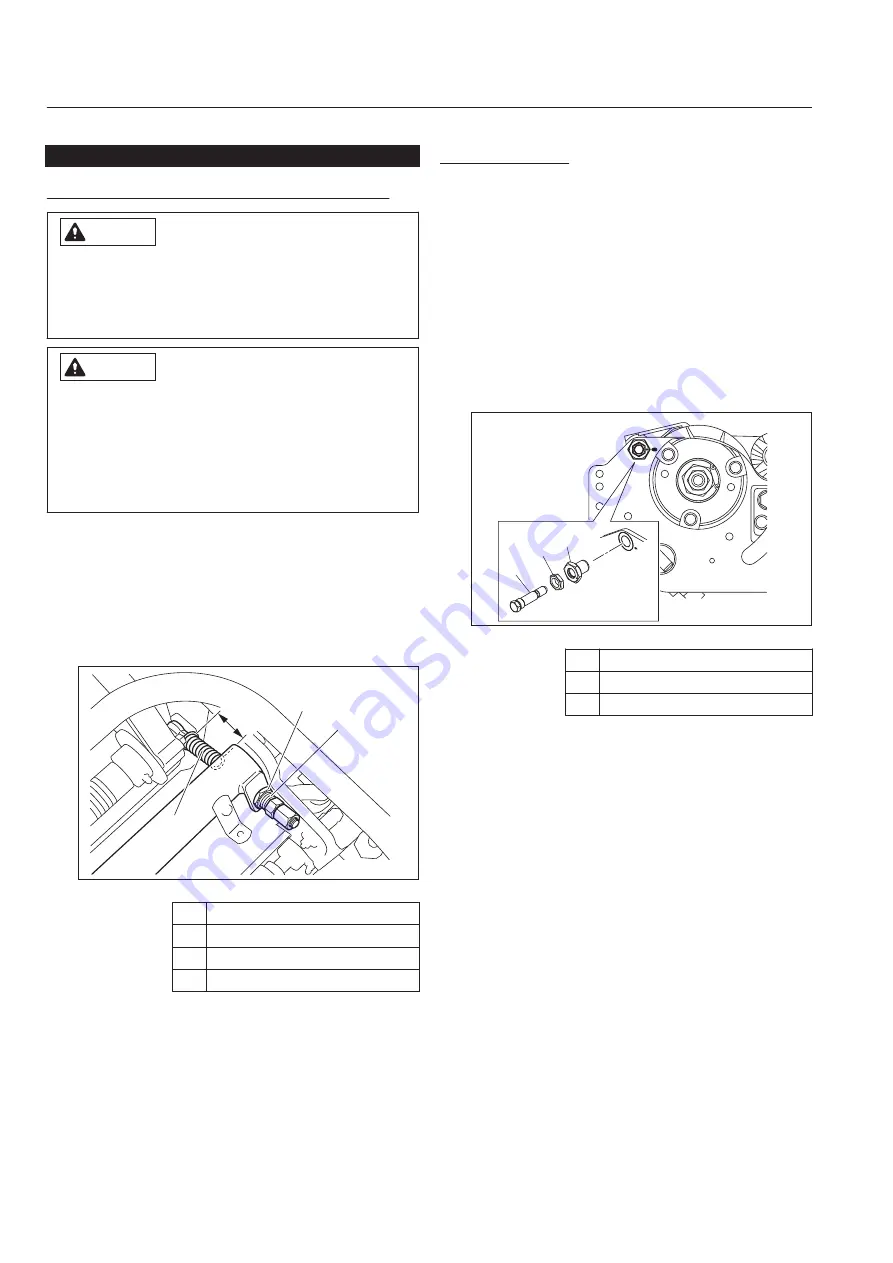
Adjusting CAM
Turn the cam bush on both sides of the bed
knife (bottom blade), and the blade can be
raised and lowered respectively by maximum
0.3 mm (0.012 in).
The above method is used when the edges of
the reel cutter (cutting cylinder) and the bed
knife (bottom blade) are not in parallel.
Check for the gap between the reel cutter
(cutting cylinder) and the bed knife (bottom
blade).
Loosen the locknut when adjusting the cam
bush.
3
2 1
69poxw-011
Adjusting CAM_001
1
Cam bush
2
Locknut
3
Cutter pin
When the gap appears on the left side.:
Turn the left cam bush clockwise to eliminate
only the gap distance.
When you raise the bed knife (bottom blade)
by 0.1 mm (0.004 in), turn the left cam bush
clockwise 30 degrees.
Once the adjustment completed, tighten the
locknut securely.
When the gap appears on the right side.:
Turn the right cam bush counterclockwise to
eliminate only the gap distance.
Once the adjustment completed, tighten the
locknut securely.
Note:
The figure below shows the situation when you
see from the left side.
The right side is mirror reversed.
1.
2.
1.
2.
LM101
Maintenance
Page 5-12
Maintenance Work
Summary of Contents for LM101
Page 6: ...LM101 Introduction ...
Page 8: ...LM101 Contents ...
Page 52: ...LM101 Handling Instructions Page 4 30 Storage ...
Page 84: ...LM101 Maintenance Page 5 32 Troubleshooting Procedures of Aftercut Appearance ...
Page 85: ......
Page 86: ......
Page 87: ......