


46
| E3 IP66 Outdoor Rated User Guide |
Version 1.25
www.bardac.com
8.3. RJ45 Connector Configuration
For full MODBUS RTU register map information please
refer to your Bardac Sales Partner. Local contacts can
be found by visiting our website:
www.bardac.com
When using MODBUS control the Analog and Digital
Inputs can be configured as shown in section
Macro Functions - Fieldbus Control Mode (P-12 = 3, 4,
7, 8 or 9) on page 43
.
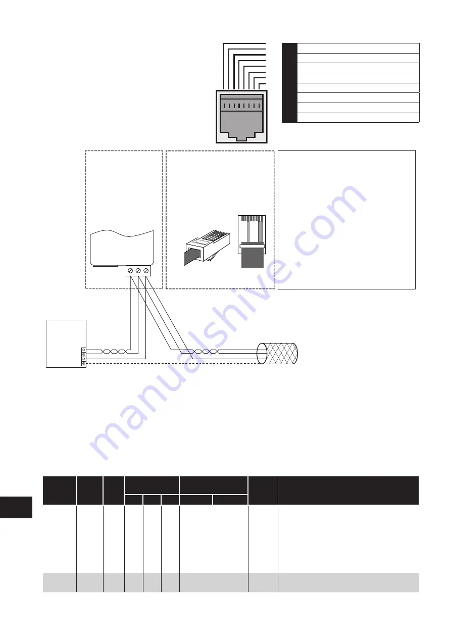
Modbus RTU
RS485 Controller
RS485+
RS485-
0 Volt / Common
Ground
NOTES
• Use 3 or 4 Conductor Twisted Pair Cable
• RS485+ and RS485- must be twisted pair
• Ensure the network taps for the drive
are kept as short as possible
• Using Option OPT-2-BNTSP-IN is
preferred
• Terminate the network cable shield at
the controller only. Do not terminate at
the drive!
• 0 Volt common must be connected
across all devices and to reference 0 Volt
terminal at the controller
• Do not connect the 0V Common of the
network to power ground
RS485+
RS485-
0 Volt / Common
Shield
OPT-2-BNTSP-IN
OPT-2-BNTSP-IN
1 2
3
RS485+
0
Volt / Commo
n
Connection to the
drive through the
option
OPT-2-BNTSP-IN
RS485-
Pin 3 – 0 Volt / Common
Pin 7 – RS485- (Modbus RTU)
Pin 8 – RS485+ (Modbus RTU)
RJ45 connector pinout
Direct connection to the drive
through the built-in RJ45 port
1 2 3 4 5 6 7 8
12345678
1
CAN -
2
CAN +
3
0 Volts
4
-RS485 (PC)
5
+RS485 (PC)
6
+24 Volt
7
-RS485 (Modbus RTU)
8
+RS485 (Modbus RTU)
Warning:
This is not an Ethernet connection.
Do not connect directly to an Ethernet port.
NOTE
For Master devices which use zero based addressing and therefore treat the first Register address as Register 0, it may be
necessary to convert the Register Numbers detailed below by subtracting 1 to obtain the correct Register address.
8.4. Modbus Register Map
Register
Number
Par.
Type
Supported
Function Codes
Function
Range Explanation
03
06
16 Low Byte High Byte
1
-
R/W
✔
✔
✔
PDO0 Control Word
0..3
16 Bit Word.
Bit 0: Low = Stop, High = Run Enable
Bit 1: Low = Decel Ramp 1 (P-04),
High = Decel Ramp 2 (P-24)
Bit 2: Low = No Function, High = Fault Reset
Bit 3: Low – No Function, High = Coast Stop Request
Bit 8: Relay control, 0 = Open, 1 = Close
Bit 9 : DO Control, 1 = Off, 0 = On
2
-
R/W
✔
✔
✔
PDO1 Frequency
Setpoint
0..5000 Setpoint frequency x10, e.g. 100 = 10.0Hz
Modbus R
TU Communications
8


