background image

Page 

1 of 50

Earth Loop Fluid

Temperatures 25 – 110

Ground Water Temperature 45 – 75

INSTALLATION INSTRUCTIONS

Bard Manufacturing Company, Inc. 
Bryan, Ohio 43506
www.bardhvac.com

Manual No.:  2100-577C
Supersedes: 2100-577B
Date: 7-25-17

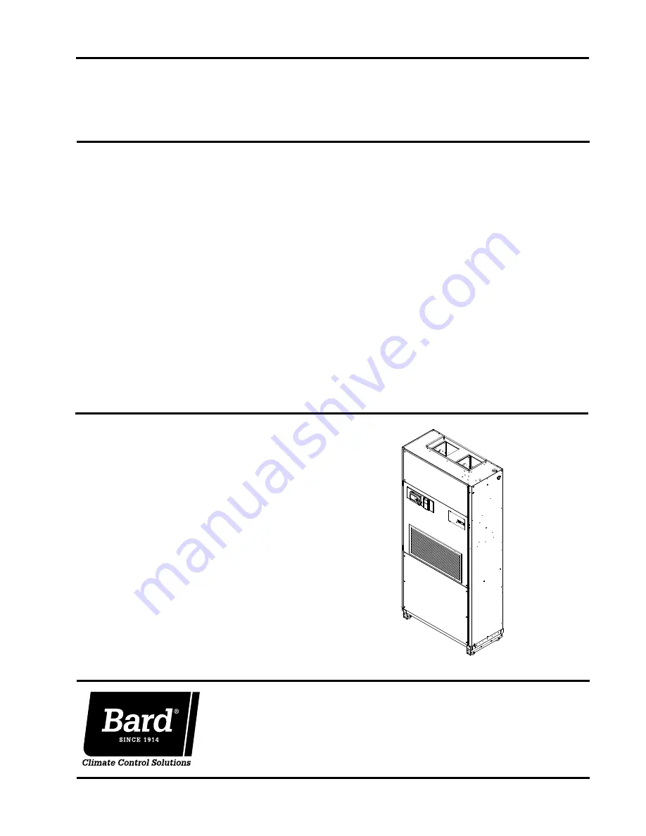
QW SERIES GEOTHERMAL R-410A

STAGED CAPACITY PACKAGED HEAT PUMP

Models:

QW2S2-A
QW2S2-B
QW2S2-C
QW2S2DA
QW2S2DB
QW2S2DC

QW3S2-A
QW3S2-B
QW3S2-C
QW3S2DA
QW3S2DB
QW3S2DC

QW4S2-A
QW4S2-B
QW4S2-C
QW4S2DA
QW4S2DB
QW4S2DC

QW5S2-A
QW5S2-B
QW5S2-C
QW5S2DA
QW5S2DB
QW5S2DC

MIS-2736

MIS-2736

Summary of Contents for QW Series

Page 1: ...06 www bardhvac com Manual No 2100 577C Supersedes 2100 577B Date 7 25 17 QW SERIES GEOTHERMAL R 410A STAGED CAPACITY PACKAGED HEAT PUMP Models QW2S2 A QW2S2 B QW2S2 C QW2S2DA QW2S2DB QW2S2DC QW3S2 A QW3S2 B QW3S2 C QW3S2DA QW3S2DB QW3S2DC QW4S2 A QW4S2 B QW4S2 C QW4S2DA QW4S2DB QW4S2DC QW5S2 A QW5S2 B QW5S2 C QW5S2DA QW5S2DB QW5S2DC MIS 2736 MIS 2736 ...

Page 2: ...stments 27 Optional CFM 28 Important Installer Note 28 Phase Monitor 28 Service Hints 28 Sequence of Operation 28 Pressure Service Ports 29 Piping Access to Unit 29 Pressure Tables 32 Optional Accessories 33 Closed Loop Earth Coupled Ground Loop Applications Circulation System Design 34 Copper Water Coil Application 34 Start Up Procedure for Closed Loop System 35 Open Loop Well System Applications...

Page 3: ...7 Remote Thermostat Wiring K Option 23 Figure 18 Fact Mounted T Stat 1 3 Opt 24 Figure 19 Fact Mounted CompleteStat Opt 25 Figure 20 CO2 Control Configuration 27 Figure 21 Fluid Connections w Ventilation Wall Sleeve 30 Figure 22 Fluid Connections w o Ventilation Wall Sleeve 31 Figure 23 Circulation System 34 Figure 24 Water Temperature and Pressure Test Procedure 35 Figure 25 Performance Model WGP...

Page 4: ...Procedures for Ground Source IGSHPA Heat Pump Systems Soil and Rock Classification for the Design IGSHPA of Ground Coupled Heat Pump Systems Ground Source Installation Standards IGSHPA Closed Loop Geothermal Systems Slinky IGSHPA Installation Guide FOR MORE INFORMATION CONTACT THESE PUBLISHERS ACCA Air Conditioning Contractors of America 1712 New Hampshire Avenue Washington DC 20009 Telephone 202 ...

Page 5: ...MODEL NUMBER Q TEC Model REVISION COLOR 4 Buckeye Gray paint X Beige paint V Platinum w Slate Front Vinyl FACTORY INSTALLED PUMP PIPING OPTIONS X None all pump and water connections field installed requires field piping to the coaxial water coil using double o ring fittings which must be ordered separately P Threaded water connections 1 DORFC 1 double o ring flow center single Grundfos UP26 99F pu...

Page 6: ...CATION DORFC PUMP ACCESS FOR FLUID CONNECTION FOR FROM BACK OF UNIT OPTIONAL HIGH VOLTAGE ELECTRICAL ENTRANCE FLUID CONNECTION FACTORY CONNECTED CONDENSATE DRAIN CONNECTION 3 4 PVC MALE ADAPTER 4 625 6 00 1 15 16 19 3 3 8 8 3 6 7 8 11 1 2 LEVEL 34 1 4 20 TO FLOOR 1 BETWEEN OPENINGS 30 7 8 5 7 16 OPTIONAL PLENUM BOX RIGHT SIDE VIEW OPTIONAL HIGH VOLTAGE BACK VIEW ELECTRICAL ENTRANCE FREEBLOW OPTION...

Page 7: ...nit can not be slid through the door then the unit will have to be put on a cart and tipped down to roll through the door It is recommended that an appliance cart be used with a strap to hold the unit on the cart The wheels of the unit must be locked If the wheels were allowed to roll the unit could roll off the cart The unit should always be carted from the left side This is the side where the co...

Page 8: ... any tags and or labels attached to the equipment While these instructions are intended as a general recommended guide they do not supersede any national and or local codes in any way Authorities having jurisdiction should be consulted before the installation is made See Page 4 for information on codes and standards Size of unit for a proposed installation should be based on heat loss calculation ...

Page 9: ...OTARY OR TOGGLE DISCONNECT ELECTRICAL ACCESS BLOW PLENUM BOX TOP SIDE AND LOCKING COVER LOW VOLTAGE OPTIONAL FREE ELECTRICAL ENTRANCE TOP REAR SIDE VENTILATION PERMANENT HIGH VOLTAGE QW2S QW3S 42 000 QW4S QW5S 48 000 28 7 8 33 7 8 103 7 8 84 1 4 X 18 9 16 35 29 1 2 33 6 1 8 17 9 16 14 to 5 FIGURE 4 Installation of Unit through Wall with Wall Sleeve ...

Page 10: ...IN MINIMUM A INSTALLATION HEIGHT 9 FT MINIMUM REQUIRED UNIT HEIGHT 7 FT 6 IN 10 INSTALLATION HEIGHT 8 FT 9 IN MINIMUM REQUIRED MINIMUM 12 IN TO DUCT BOTTOM 2 IN MINIMUM FROM DUCT FLANGE FLOOR MIS 2741 A MODEL A QW2S QW3S 25 QW4S QW5S 30 DUCT FIXED CEILING DUCT FLANGE SUSPENDED CEILING FIGURE 5 Installation with Free Blow Plenum ...

Page 11: ...al the duct work above the unit to the ceiling This extends 20 above the unit for a total height above the floor of 10 7 8 The unit is equipped with a variable speed indoor blower motor which increases in speed with an increase in duct static pressure The unit will therefore deliver proper rated airflow up to the Maximum ESP shown in Table 4 However for quiet operation of the air system the duct s...

Page 12: ...he wall If the drain is to be routed through an unconditioned space it must be protected from freezing The drain line must be able to be removed from the unit if it is necessary to remove the unit from the wall MIS 2743 FLOOR OPTION DRAINING EXTERNAL DRAIN TUBE DRAIN HOSE FRONT VIEW WITH CONDENSER DOOR REMOVED ALTERNATE LOOP TO FORM A P TRAP ...

Page 13: ...d that the mist eliminator be inspected annually and serviced as required The mist eliminator can be inspected from the outside of the building by looking through the outdoor grille The mist eliminator can be serviced from the outside The outdoor grille must be removed to do so The mist eliminator can be cleaned by washing with soap and water The excess water should be shaken off the mist eliminat...

Page 14: ...e there is a power connector for the lower blower assembly To Figure 9 Removal of the Q TEC Energy Recovery Ventilator FRONT FILL MOUNTING SCREWS LOWER BLOWER ASSEMBLY POWER CONNECTOR POWER CONNECTORS disconnect this plug the tabs on both sides of the plug must be squeezed to release the plug While squeezing the tabs pull the plug out of the socket 4 The QERV is plugged into the unit on the right ...

Page 15: ...g connections are to be within the confines of this bracket See Figure 1 for cabinet openings and location of fluid coil connection points 2 Position the unit in front of the wall mounting bracket 3 Remove the locking screws from the wheels see Figure 10 4 Roll the unit up to the wall mounting bracket The unit must be level from side to side If any adjustments are necessary shim up under the rolle...

Page 16: ... of 50 FIGURE 11 Unit Mounting without Ventilation Wall Sleeve BRACKET WALL MOUNTING BASE TRIM SIDE TRIM CUT TO LENGTH 41 ADJUSTABLE SIDE TRIM EXTENSION KIT ORDERED SEPARATELY SIDE TRIM EXTENSION MIS 2744 A BASE TRIM EXTENSION ...

Page 17: ...Manual 2100 577C Page 17 of 50 FIGURE 12 Component Location WIRE ENTRANCE SIDE FIELD TERMINAL BLOCK REMOTE THERMOSTAT INDOOR DUAL BLOWERS CONTROL BOX CIRCUIT BREAKER PANEL MIS 2745 ...

Page 18: ...and 3 Phase Equipment Dual Primary Voltage Transformers All equipment leaves the factory wired on 240V tap For 208V operation reconnect from 240V to 208V tap The acceptable operating voltage range for the 240 and 208V taps are as noted in Table 2 The standard Climate Control Option X is a remote thermostat connection terminal block See Figure 14 for wiring diagram Compatible thermostats are listed...

Page 19: ... for ventilation during occupied programming conditions and feeds through Pin 5 of Plug P2 The W2 terminal is the electric heat signal and feeds through Pin 9 of Plug P2 The W1 E terminal is the emergency heat signal and feeds through Pin 3 of Plug P2 The L terminal is used as an input terminal when a CS2000 infrared occupancy device is used It feeds through Pin 12 of Plug P2 The D terminal is use...

Page 20: ...r Temp and Humidity Part 8403 060 C 4115 102 E A W2 Y1 R Y2 Temp and Humidity Controller D YO Orange Orange Yellow Green Brown Brown White Red White PLUG 2 PLUG 1 Red Red Yellow Black White 1 Terminal 1 Black Strip WITH CO2 CONTROL FOR ENERGY RECOVERY VENTILATOR WITH CO2 CONTROL DO NOT CONNECT A OCCUPANCY INPUT BETWEEN THERMOSTAT AND LOW VOLTAGE TERMINAL STRIP DO MAKE THIS CONNECTION WHEN APPLYING...

Page 21: ...hermostat Wiring Diagram D Thermostat Option PLUG 2 Purple White D YO Pink Black White Red White Brown Blue Yellow Orange Brown White Purple Red Yellow Temp and Humidity Controller Part 8403 060 L W1 E G O B R Y1 W2 A Y2 C 4115 100 A 2 12 10 11 9 8 7 6 5 4 3 1 ...

Page 22: ...e Pink Purple Purple White Yellow Yellow W1 E L G D YO Part 8403 060 CO2 OUT 5 C 24VAC Y2 Controller A 1 W2 2 Y1 3 R 4 O B Part 8403 067 6 Temp and Humidity CO2 Controller TEMP OUT Orange Orange Orange Yellow Green Green Brown Brown White 4115 101 E FIGURE 16 Factory Mounted Thermostat and CO2 Vent Control Wiring Diagram H Thermostat Option ...

Page 23: ...ed Yellow Red White PLUG 2 Black Black White 2 1 2 Black FOR DEHUMIDIFICATION MODELS EQUIPPED WITH FACTORY HOT GAS REHEAT CONNECT SIGNAL FOR HUMIDISTAT TO PURPLE WHITE WIRE FOR ENERGY RECOVERY VENTILATOR WITH CO2 CONTROL DO NOT CONNECT A OCCUPANCY INPUT BETWEEN THERMOSTAT AND LOW VOLTAGE TERMINAL STRIP DO MAKE THIS CONNECTION WHEN APPLYING A COMMERCIAL ROOM VENTILATOR WITH CO2 CONTROL 4115 105 B F...

Page 24: ...Pink Purple White Purple OR CS9BE THO Black White COMPLETESTAT TEMPERATURE HUMIDITY AND OCCUPANCY CONTROLLER BARD PART CS9B THO 4115 108 Orange Yellow Brown Brown White Red White Red White 7 Red White 7 Red White 7 Red Yellow 2 Black White FIGURE 18 Factory Mounted Completestat with Occupancy Sensing and Temperature Humidity Control 1 3 Option Wiring Diagram ...

Page 25: ...Purple White Purple OR CS9BE THOC Black White COMPLETESTAT TEMPERATURE HUMIDITY OCCUPENCY AND CO2 CONTROLLER BARD PART CS9B THOC 4115 109 Orange Yellow Brown Brown White Red White Red White Red White Red White 7 7 7 Red Yellow 2 Black White FIGURE 19 Factory Mounted Completestat with Occupancy Sensing and Temperature Humidity CO2 Control 2 4 Option Wiring Diagram ...

Page 26: ...s and prevents restart until the delay on break and delay on make periods have expired During routine operation of the unit with no power interruptions the compressor will operate on demand with no delay High Pressure Switch and Lockout Sequence If the high pressure switch opens the compressor contactor will de energize immediately The lockout timer will go into a soft lockout and stay in soft loc...

Page 27: ...2 7 850 3 8 900 4 9 950 5 10 1000 6 11 1050 7 Settings Recommended Default RON Not Used ROF Not Used DSP C CT UNI US US COL 700 0 COH 1500 2000 TOL Not Used TOH Not Used BAR See Instrution with Controller For High Altitude Installations CAL Used for Field Calibration 1 Damper should be fully closed at 700 ppm if not Potentiometer R7 can be adjusted clockwise CW to close it If it is fully closed at...

Page 28: ...easing operating costs and noise levels 2 Check all power fuses or circuit breakers to be sure that they are the correct rating 3 The heat pump wall thermostats perform multiple functions Be sure that all function switches are correctly set for the desired operating mode before trying to diagnose any reported service problems SEQUENCE OF OPERATION COOLING A 24V solenoid coil on the reversing valve...

Page 29: ...vice door as well as later in this Manual Table 5 It is imperative to match the correct pressure chart to the unit by model number All upper service doors must be attached to obtain proper reading The service ports are in the lower compressor section on the tubing adjacent to the compressor This unit employs high flow Coremax valves instead of the typical Shrader type valves WARNING Do NOT use a S...

Page 30: ...SHIPPED WITH UNIT CEILING SIDE TRIM PIECES SHIPPED WITH UNIT IF THE WALL THICKNESS IS LESS THAN 14 BUT GREATER THAN 8 A SIDE TRIM EXTENSION KIT QSTX42 IS REQUIRED REFER FLUID ACCESS FROM SLEEVE TOP OF UNIT SLEEVE FLUID ACCESS 3 x 8 FLUID ACCESS REAR OF UNIT BACK OF UNIT MIS 2746 FROM FLOOR 35 x 29 1 2 FLOOR FROM EACH SIDE FLUID ACCESS WALL OPENING FROM EACH SIDE OPENING IN MOUNTING BRACKETS SHIPPE...

Page 31: ...t without Ventilation Wall Sleeve 23 1 2 8 1 2 66 1 2 4 LEFT BRACKET REMOVED FOR FLOOR FLUID ACCESS FROM FLOOR FLUID ACCESS FROM TOP CLARITY WALL BRACKET OPENING IN REAR OF UNIT 3 x 8 BACK OF UNIT MIS 2747 WATER LINES WALL BRACKET TOP VIEW WALL BRACKET WALL LOCATION ...

Page 32: ... 86 371 93 382 100 394 109 408 119 421 128 435 137 448 146 462 156 475 165 489 Model Return Air Temperature Pressure PART LOAD COOLING Fluid Temperature Entering Water Coil F 30 F 35 F 40 F 45 F 50 F 55 F 60 F 65 F 70 F 75 F 80 F 85 F 90 F 95 F 100 F 105 F 110 F QW2S 75 DB 62 WB Low Side High Side 105 120 109 135 113 150 117 165 121 179 125 194 129 209 133 224 137 239 139 259 141 279 143 299 144 3...

Page 33: ...S QW5S QPBX48 10 V Platinum Vinyl QPBX48 10 4 Gray Paint QPBX48 10 X Beige Paint Use with QPB48 or QPBS48 adjusts to ceilings up to 10 5 Cabinet Extensions for Ducted Applications Unit Compatibility QCX10A V Platinum Vinyl QCX10A 4 Gray Paint QCX10A X Beige Paint 20 height adjusts for ceilings up to 9 7 add QPBX42 9 for 9 7 to 10 3 finished ceiling heights QW2S QW3S QCX15A V Platinum Vinyl QCX15A ...

Page 34: ... of head loss of the entire system in order FIGURE 23 Circulation System to provide the required flow through the heat pump Insufficient flow through the heat exchanger is one of the most common causes of system failure Proper system piping design and circulator selection will eliminate this problem Bard supplies a work sheet to simplify head loss calculations and circulator selection Refer to Cir...

Page 35: ... trapped air or a restriction in the piping circuit 8 Start the unit in cooling mode by moving the thermostat switch to cool Fan should be set for AUTO 9 Check the system refrigerant pressures against the cooling refrigerant pressure table in the installation manual for rated water flow and entering water temperatures If the refrigerant pressures do not match check for airflow problem then refrige...

Page 36: ...Manual 2100 577C Page 36 of 50 Manual 2100 577 Page 36 of 50 FIGURE 26 PERFORMANCE MODEL DORFC 2 LOOP PUMP MODULE FIGURE 25 PERFORMANCE MODEL DORFC 1 LOOP PUMP MODULE ...

Page 37: ...the water flow direction indicated by the arrow on the side of the valve body Table 7 is a table showing the flow rate of each valve Two constant flow rate valves may be installed in parallel to increase the flow For example when a 8603 007 6 GPM and 8603 011 5 GPM are installed in parallel the total flow will be 11 GPM Figure 27 Piping Diagram TABLE 7 Constant Flow Valves The pressure drop throug...

Page 38: ... power disconnect to ON Except as required for safety while servicing do not open the unit disconnect switch 4 Check system airflow for obstructions A Move thermostat fan switch to ON Blower runs B Be sure all registers and grilles are open C Move thermostat fan switch to AUTO Blower should stop 5 Fully open the manual inlet and outlet valves 6 Check water flow A Connect a water flow meter to the ...

Page 39: ...ler 3 Corrosion of Metal Corrosion of metal parts results from either highly corrosive water acid water generally not the case with ground water of galvanic reaction between dissimilar metals in the presence of water By using plastic plumbing or dielectric unions galvanic reaction is eliminated The use of corrosion resistant materials such as the Cupronickel coil through the water system will redu...

Page 40: ... suspended in the dry well casing Jet pumps and other types of suction pumps normally consume more electrical energy than similarly sized submersible pumps Pipe the unit the same as a water well system D Size the pump to provide necessary GPM for the ground water heat pump A 12 GPM or greater water flow rate is required on all modes when used on this type system E A pressure tank should be install...

Page 41: ...1 of 50 FIGURE 29 Water Well System 12 to 15 LAKE or POND WATER LEVEL GRAVEL FILL WELL CAP ELECTRICAL LINE PITLESS ADAPTER TO PRESSURE TANK SUBMERSIBLE PUMP PERFORATED PLASTIC CASING DROP PIPE WATER SUPPLY LINE 15 to 20 DEEP ...

Page 42: ...he desired temperature In milder climates a flooded tower concept is often used This concept involves adding makeup water to the cooling tower sump to maintain the desired loop temperature Units are equipped with double O ring female pipe thread fittings Consult the specification sheets for sizes Teflon tape sealer should be used when connection to the unit to ensure against leaks and possible con...

Page 43: ...Manual 2100 577C Page 43 of 50 FIGURE 30 Water Source Heat Pump ...

Page 44: ...Manual 2100 577C Page 44 of 50 FIGURE 31 Water Source Heat Pump ...

Page 45: ...ide while the low side shell and suction line contains pressure the pressurized refrigerant and oil mixture could ignite when it escapes and contacts the brazing flame To prevent this occurrence it is important to check both the high and low side with manifold gauges before unbrazing WARNING Both the high and low side of the scroll compressor must be checked with manifold gauges before unbrazing s...

Page 46: ...if it s air noise cabinet duct or motor noise interview customer if necessary Air noise High static creating high blower speed Is airflow set properly Does removing filter cause blower to slow down Check filter Use low pressure drop filter Check correct duct restrictions Symptom Cause Procedure Noisy blower or cabinet Check for loose blower housing panels etc High static creating high blower speed...

Page 47: ...trol module is now completely detached from the motor Verify with a standard ohmmeter that the resistance from each motor lead in the motor plug just removed to the motor shell is 100K ohms Refer to Figure 7 Measure to unpainted motor end plate If any motor lead fails this test do not proceed to install the control module THE MOTOR IS DEFECTIVE AND MUST BE REPLACED Installing the new control modul...

Page 48: ...d Motor Winding Defective Air Volume Low Air Filters Dirty Undersized or Restricted Ductwork Auxillary Heat Upstream of Coil Compressor Will Not Run No Power at Contactor Compressor Will Not Run Power at Contactor Compressor Hums But Will Not Start Compressor Cycles on Overload Thermostat Check Light Lite Lockout Relay Compressor Off on High Pressure Control Compressor Off on Low Pressure Control ...

Page 49: ...led By Date Installed 5 User s Owner s Name Address 6 Unit Location WATER SYSTEM INFORMATION 7 Open Loop System Water Well Closed Loop System A If Open Loop where is water discharged 8 The following questions are for Closed Loop systems only A Closed loop system designed by B Type of antifreeze used Solution C System type Series Parallel D Pipe Material Nominal Size E Pipe Installed 1 Horizontal T...

Page 50: ...t line side of contactor A 19 Amperage at compressor common terminal A 20 Suction line temperature 6 from compressor F 21 Superheat at compressor F 22 Liquid line temperature at metering device F 23 Coil subcooling F INDOOR SIDE DATA Cooling Heating 24 Dry bulb temperature at air entering indoor coil F 25 Wet bulb temperature of air entering indoor coil F 26 Dry bulb temperature of air leaving ind...

Reviews: