background image

R5911438 /09

UDM

82

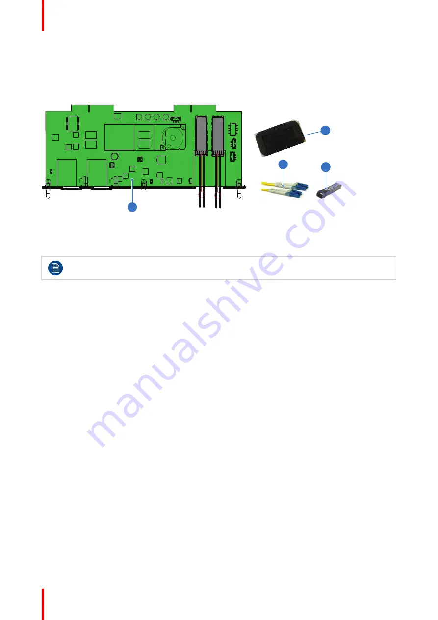
7.1 Use case 1: SFP+ trans Fiber
connection (integrated or separated)

SFP+ trans Fiber connection (integrated or separated)

1

3

2

4

Image 7–1

1

SFP input board

2

SFP+ fiber transceiver

3

Optional breakout Optical adapter

4

Dustproof Gasket

Barco delivers only the SFP input and SFP+ fiber transceivers. The customer has to buy the SFP+
transceiver and the optional breakout adapter or the fiber integrated cable.

How to configure the SFP input

1.

Remove the plate covering the access to the SFP cages.

2.

Insert the SFP+ transceivers

3.

Connect the breakout adapter.

4.

Install the SFP input in its slot of the Input & Communication module. See procedure

“Installation of an

input board”, page 55

.

5.

Insert the dust proof gasket in the opening where the covering plate was removedd

Pulse SFP input use cases

Summary of Contents for UDM

Page 1: ...ENABLING BRIGHT OUTCOMES Installation manual UDM...

Page 2: ...Registered office Barco NV President Kennedypark 35 8500 Kortrijk Belgium www barco com en support www barco com Barco NV Beneluxpark 21 8500 Kortrijk Belgium www barco com en support www barco com...

Page 3: ...co must be informed immediately in writing of any complaints The period of guarantee begins on the date of transfer of risks in the case of special systems and software on the date of commissioning at...

Page 4: ......

Page 5: ...29 3 1 Installation requirements 30 3 2 Unpacking the projector 32 3 3 Initial inspection 34 3 4 Projector orientations 35 3 5 Projector positioning 37 3 6 Projector shift and tilt range 38 3 7 Lens...

Page 6: ...77 6 1 Flight case 78 6 2 Rigging frame 79 7 Pulse SFP input use cases 81 7 1 Use case 1 SFP transceiver Fiber connection integrated or separated 82 7 2 Use case 2 Neutrik OpticalCon Duo SFP transceiv...

Page 7: ...tions to prevent damage to the UDM projector Ensure that you understand and follow all safety guidelines safety instructions and warnings mentioned in this chapter before installing the UDM projector...

Page 8: ...ety standards These safety standards impose important requirements on the use of safety critical components materials and insulation in order to protect the user or operator against risk of electric s...

Page 9: ...Users definition Throughout this manual the term SERVICE PERSONNEL refers to Barco authorized persons having appropriate technical training and experience necessary to be knowledgeable of potential ha...

Page 10: ...cts enter into the vents and openings of the set Do not expose this projector to rain or moisture The projector is designed for indoor use only Never operate the unit outdoors Do not immerse or expose...

Page 11: ...mount 2 safety cables See installation manual for the correct use of these cables Do not place this equipment on an unstable cart stand or table The product may fall causing serious damage to it and p...

Page 12: ...correct airflow is maintained and that the projector complies with Electromagnetic Compatibility EMC and safety requirements it should always be operated with all of it s covers in place Slots and op...

Page 13: ...ctions are followed Adjust only those controls that are covered by the operating instructions since improper adjustment of the other controls may result in damage and will often require extensive work...

Page 14: ...14 HAZARD DISTANCE CONSULT SAFETY MANUAL THIS PRODUCT IS IN CONFORMITY WITH PERFORMANCE STANDARDS FOR LASER PRODUCTS UNDER 21 CFR 1040 EXCEPT WITH RESPECT TO THOSE CHARACTERISTICS AUTHORIZED BY VARIAN...

Page 15: ...another individual s shoulders within the HD These values are minimum values and are based on the guidance provided in IEC 62471 5 2015 section 6 6 3 5 The installer and user must understand the risk...

Page 16: ...h that the bottom plane of the Hazard distance Zone shall be no lower than 3 meters above the floor Horizontal clearance to the hazard distance zone shall be not less than 2 5 meters Any human access...

Page 17: ...beam exposure HDreflection the distance that has to be kept restrictive related to the reflected light from the rear projection screen HDdiffuse the relevant distance to be considered while observing...

Page 18: ...R5911438 09 UDM 18 1 6 HD in function of modifying optics Hazard distance Image 1 5 Safety information...

Page 19: ...Barco declares that the radio equipment type UDM is in compliance with Directive 2014 53 EU The full text of the EU declaration of conformity is available at the following internet address https www...

Page 20: ...DM 20 1 8 Compliance UK Compliance UK This product is fit for use in the UK Authorised Representative Barco UK Ltd Address Building 329 Doncastle Road Bracknell RG12 8PE Berkshire United Kingdom Safet...

Page 21: ...ual Product manuals and documentation are available online at www barco com td Registration may be required follow the instructions given on the website IMPORTANT Read Installation Instructions before...

Page 22: ...R5911438 09 UDM 22 Safety information...

Page 23: ...t stages in the installation process that has to be followed in chronological order to set the UDM projector up and running The stages are grouped in three processes Preparation Installation and Optio...

Page 24: ...ation requirements page 30 3 Unpack the projector or pull out the projector from its flight case See chapter Unpacking the projector page 32 or see chapter Flight case page 78 4 In case of a first ins...

Page 25: ...requirements such as the hazard distance restriction zone etc See safety chapter High Brightness precautions Hazard Distance page 15 3 Installation of the lens For detailed instructions see Lens inst...

Page 26: ...e Focus Zoom and Shift buttons of the RCU Lens adjustment button of the Local Keypad For detailed instructions see user guide of the projector Projector Toolset control software For detailed instructi...

Page 27: ...ation of the WiFi GSM module For installation instructions see installation manual of the WiFi GSM module 3 Installation of the distance meter module For installation and adjusting instructions see in...

Page 28: ...R5911438 09 UDM 28 Installation process...

Page 29: ...tion requirements for the projector such as minimum and maximum allowed ambient temperature humidity conditions required safety area around the installed projector required power etc In addition caref...

Page 30: ...jector Image 3 1 CAUTION Keep the air inlets and outlet at all times free Make sure there is a minimum distance of 40 cm 15 7 in between the air outlet and the nearest solid object Cooling requirement...

Page 31: ...s and damage sensitive optoelectronics components Failure to take suitable precautions to protect the projector from the effects of persistent and prolonged air contaminants will culminate in extensiv...

Page 32: ...c foam When the projector arrives the installation site it needs to be removed from the box and pallet in a safe manner without damaging the projector After unpacking let the projector acclimatize to...

Page 33: ...For maximum protection repack your projector as it was originally packed at the factory A plastic lens holder cover is placed into the lens opening of the projector It s recommended to reuse this cove...

Page 34: ...ld be notified as soon as possible Box content After unpacking the projector it is recommended to check if all following items were included One power cord of 4 m EUR 4m C19 One quick start guide One...

Page 35: ...Front Table F T 2 Front Ceiling F C 3 Rear Table R T 4 Rear Ceiling R C Front projection The projector is installed either in a table mount or ceiling mount configuration at the same side of the scre...

Page 36: ...R5911438 09 UDM 36 Some lenses e g UST lenses may require that the projector orientation needs to be adapted for the desired outcome Prepare to install...

Page 37: ...D B SW Image 3 7 On axis off axis projection The position of the projector with reference to the screen may also be different depending on the installation Basically the projector can be positioned in...

Page 38: ...excellently Configuring the projector outside these shift ranges will result in a slight decline of image quality U 130 100 40 40 D L R P F U D SIDE VIEW P F 130 100 TOP VIEW P F L R 40 40 Image 3 8 V...

Page 39: ...39 R5911438 09 UDM 360 360 Image 3 9 Prepare to install...

Page 40: ...ebsite https lenscalculator barco com to determine the possible lenses for your configuration The Lens Calculator window opens Image 3 10 Lens calculator The Lens Calculator can also be used to determ...

Page 41: ...llowing TLD lenses can be used on the UDM projector Do not use other types of lenses Use the online Lens Calculator tool to determine the possible lenses for your configuration See Lens selection page...

Page 42: ...to account active lenses at the moment of release of this manual Lenses that have become end of life or end of service are not taken into account Consult the Barco website for the most up to date info...

Page 43: ...yet registered click on New to myBarco and follow the instructions With the created login and password it is possible to enter the Partner zone of Barco When your login is correct the Partner zone is...

Page 44: ...R5911438 09 UDM 44 Prepare to install...

Page 45: ...tting the projector addresses 51 4 6 Alignment of a table mounted projector 52 4 7 Alignment of projector in the rigging frame 53 4 8 Wall or ceiling mount without rigging frame 54 4 9 Installation of...

Page 46: ...gernail a little backwards 1 and pull at the same time the cover upwards 2 1 2 Image 4 1 2 Insert the two AA size batteries making sure the polarities match the and marks inside the battery compartmen...

Page 47: ...tery type Use two AA size batteries There is a risk of explosion if the battery is replaced with an incorrect type CAUTION Replace the battery as explained above There is a risk of explosion if the ba...

Page 48: ...ide of the power cord to the local power net 4 If Overvoltage lights up when connecting the powercord do NOT press the power switch to on Pull out the powercord and check the mains voltage 5 If Overvo...

Page 49: ...the Button pressed indicator lights up continuously proximately 5 seconds 2 Enter the address with the digit buttons within the time the indicator lights up also proximately 5 seconds Note That addre...

Page 50: ...its default value 0 How to use the XLR connector 1 Remove the XLR cover by pulling it backwards Image 4 5 2 Connect a cable with XLR plug into the XLR connector of the RCU 3 Connect the other end of...

Page 51: ...h projector has its own address The factory default individual projector address is 0 When the address is set the projector can be controlled with the RCU Only addresses between 0 and 31 are supported...

Page 52: ...ize of the screen 2 Project one of the internal hatch patterns on the screen 3 Turn the adjustable feet in or out until the projected hatch pattern has a perfect rectangle shape and is leveled Image 4...

Page 53: ...Turn the skew knob at the rear to adjust the rotation 1 Image 4 8 Tilt the projector 1 Turn the tilt adjustment knob at the rear to tilt the projector 1 Image 4 9 Rotating the projector 1 Turn the ro...

Page 54: ...onal rigging equipment are the same as for the adjustable feet at the bottom of the projector Attachment point specifications Attachment point screw dimension M10 Thread engagement Min 15mm Max 30mm T...

Page 55: ...ojector and unplug the power cord of the projector 2 If a dummy plate is mounted remove the dummy plate Release the 3 captive screws of the dummy plate to remove it 2 3 Push the input module in the In...

Page 56: ...installed module Use the complete software package to install the firmware via Projector Toolset or USB stick Tip When a complete new software image is placed on the projector all programmable compone...

Page 57: ...off the projector and unplug the power cord of the projector 2 Release the 3 captive screws of the input module 4 3 4 Image 4 15 3 Pull out the input module of the Input Communication module using the...

Page 58: ...ons With the created login and password it is possible to log in where you can download the software 3 Download the latest firmware format fw from Barco s website in the same way as for Projector Tool...

Page 59: ...you can download the software 3 Place the firmware file on a clean USB flash drive Note Make sure the flash drive is FAT32 compatible no other files are on the flash drive 4 Plug the flash drive in t...

Page 60: ...R5911438 09 UDM 60 Installation procedures...

Page 61: ...61 R5911438 09 UDM Lenses 5...

Page 62: ...rence 2 as illustrated 1 2 3 Image 5 1 Lens installation preparation 2 Remove the dust cover from the lens opening Image 5 2 Tip While not placed in the projector place the dust cover in a lockable pl...

Page 63: ...not release the lens yet as the lens may fall out of the lens holder 7 Secure the lens in the lens holder by sliding the primary lens lock handle into the locked position away from the lens power supp...

Page 64: ...mm 4 mm 4 Image 5 5 How to install the lens safety cable 1 Ensure that the safety cable and its accessories are in good condition not damaged 2 Paste four cable clips on the lens body between motor bl...

Page 65: ...of the cable around the lens counterclockwise Click the cable into every clip it passes in this loop Note Make sure the cable passes between the lens and the cable bundle 5 Slide the cable through th...

Page 66: ...the truss or rigging frame Caution The safety cable is mounted as backup so that the drop distance is as small as possible Keep the possible drop distance of the lens as short as possible How to mount...

Page 67: ...Make sure that both a part of the loop end and the outgoing part of the safety cable are placed in the enclosure 6 Close the U bolt and tighten it Note Make sure the safety cable is tightened around...

Page 68: ...ked position as illustrated Image 5 15 Image 5 15 Unlock the lens 2 Pull down the secondary lock on the lower left side of the lens holder as illustrated Image 5 16 3 Gently pull the lens out of the l...

Page 69: ...69 R5911438 09 UDM It s recommended to place the dust cover of the original projector packaging back into the lens opening to prevent intrusion of dust Image 5 17 Lenses...

Page 70: ...ation For this reason the UST lenses that can be used on both generations rental projectors are designed with a motor block that can easily be rotated around the lens body This allows that the lens ou...

Page 71: ...p end of the safety cable into one of the clips 4 Slide the rest of the cable around the lens Click the cable into every clip it passes in the loop 5 Slide the cable through the loop end at the beginn...

Page 72: ...lens lock handle into the locked position 8 Check if the lens touches the front plate of the Lens Holder 9 Check if the lens is really secured by trying to pull the lens out of the lens holder Image...

Page 73: ...ot motorized Manual adjustment is needed 3 Rotate the focusing gear Ring B to get good focus of CENTER Note Ring B is motorized Use the remote control or local keypad of the projector to adjust T A B...

Page 74: ...tools Allen wrench 2 5 mm Required parts Set screw M5x8 DIN915 Rotate the motor block of the lens 1 Remove the eight screws reference 1 as illustrated Use a 2 5 mm Allen wrench 1 Image 5 27 2 Rotate t...

Page 75: ...75 R5911438 09 UDM 5 5 1 5 mm Image 5 30 If no turn the set screw out of the mounting plate until it doesn t exceed on the other side of the mounting plate 5 5 0 mm Image 5 31 Lenses...

Page 76: ...R5911438 09 UDM 76 Lenses...

Page 77: ...11438 09 UDM 6 1 Flight case 78 6 2 Rigging frame 79 About flight case and rigging frame The projector can also be delivered with rigging frame installed inside a flight case Flight case and rigging f...

Page 78: ...caster wheels provided with breaks and the eight handles make the UDM flight case easy to handle The floor of the flight case wagon is equipped with two small covered compartments to store the remote...

Page 79: ...UDM series multifunctional rigging frame is designed for the Barco UDM projectors and can not be used for other equipment See rigging frame specific documentation for how to install the projector in t...

Page 80: ...R5911438 09 UDM 80 Flight case and rigging frame...

Page 81: ...e 3 Neutrik OpticalCon Quad SFP transceiver internal fiber 84 7 4 Use case 4 Loop through mode 85 About this chapter This chapter describes the several use cases of the SFP input Each use case require...

Page 82: ...iber transceivers The customer has to buy the SFP transceiver and the optional breakout adapter or the fiber integrated cable How to configure the SFP input 1 Remove the plate covering the access to t...

Page 83: ...the optional breakout adapter or the fiber integrated cable How to configure the SFP input 1 Remove both plates covering the access to the Neutrik connector locations 2 Mount the Neutrik OpticalCon Du...

Page 84: ...ceiver and the optional breakout adapter or the fiber integrated cable How to configure the SFP input 1 Remove one plate covering the access to a Neutrik connector location 2 Mount the Neutrik Optical...

Page 85: ...FP input 1 Remove both plates covering the access to a Neutrik connector locations 2 Mount the Neutrik OpticalCon Quad connector and the Neutrik OpticalCon Duo 3 Remove the plate covering the access t...

Page 86: ...R5911438 09 UDM 86 Pulse SFP input use cases...

Page 87: ...aintain or to service The procedures in this chapter describe with detailed step by step actions and illustrations how to remove or install the projector covers WARNING Switch off the projector and di...

Page 88: ...ylock tabs Required tools Flat screwdriver 5 mm Unlocking 1 Push down the inner side of the easylock with a screwdriver Image 8 1 As a result the lock jumps loose Locking 1 Ensure that the cover is in...

Page 89: ...he front side and rear covers Remove the lens before removing the front cover Required tools Flat screwdriver 5 mm How to remove the covers 1 Remove the lens 2 Release the easylocks and remove the cov...

Page 90: ...8 3 Removal of top cover Required tools Torx screwdriver T20 How to remove the top cover 1 Release the 6 Torx screws indicated in the illustration 1 1 1 Image 8 7 2 Lift up the cover of the projector...

Page 91: ...horizontally and it will still fit the attachment points But then the air intake for the light processor fan will be out of position and by that the cooling will not be sufficient Install covers The i...

Page 92: ...R5911438 09 UDM 92 Projector covers...

Page 93: ...93 R5911438 09 UDM A 1 Dimensions of the projector 94 A 2 Dimensions of the rigging frame 95 A 3 Dimensions of the flight case 96 Dimensional drawings A...

Page 94: ...R5911438 09 UDM 94 A 1 Dimensions of the projector Dimensional drawing 676 491 540 339 7 185 7 15 3 175 5 725 Image A 1 Dimensions are given in millimeters Dimensional drawings...

Page 95: ...M A 2 Dimensions of the rigging frame Dimensional drawing 711 Overall dimension 889 Overall dimension 642 CC Rigging points 819 CC Rigging points 463 Image A 2 Dimensions are given in millimeters Dime...

Page 96: ...R5911438 09 UDM 96 A 3 Dimensions of the flight case Dimensional drawing 866 1043 736 5 436 5 300 Image A 3 Dimensions are given in millimeters Dimensional drawings...

Page 97: ...t becomes lower than the applicable exposure limit on the cornea or on the skin The light beam is considered to be unsafe for exposure if the distance from a person to the light source is less than th...

Page 98: ...R5911438 09 UDM 98 Glossary...

Page 99: ...99 R5911438 09 UDM Allen wrench 2 5 mm Cutter knife Flat screwdriver 5 mm Phillips screwdriver PH1 Torx screwdriver T10 Torx screwdriver T20 List of tools...

Page 100: ...R5911438 09 UDM 100 List of tools...

Page 101: ...roduct manual 21 Projector Toolset 43 E Enclosed projection 17 Environment conditions 30 F Flight case 77 Weight 78 Front cover 89 G General Considerations 8 H Hazard Distance 15 17 Modifying optics 1...

Page 102: ...0 Procedures Install 45 Product safety labels 14 Projector Address Setting 51 Off axis 37 On axis 37 Orientations 35 Positioning 37 Shift 38 Shift range 38 Tilt 38 Weight 31 Projector Toolset 43 Pulse...

Page 103: ...2 Use cases SFP input 81 85 User definition 9 UST lens 70 Introduction 70 UST Lens Safety cable 71 V Vertical tilt range 38 W Warnings Cooling liquid circuit 11 Weight Flight case 78 Projector 31 Rigg...

Page 104: ...R5911438 09 UDM 104 Index...

Page 105: ......

Page 106: ...www barco com R5911438 09 2023 02 28...

Reviews: