

S3-4K
– Screen Management System
Quick Start Guide
Visibly yours
Barco Technical Support:
USA
: +1 (866) 374-7878 /
EMEA :
0800 90 0410
CHINA :
40088 22726
www.barco.com/support/eSupport.aspx
Input Cards
Output Cards
Link Card
MVR
Link Card
- 2 High speed CXP connectors
Notes:
-Each Input and Output card supports
one 4K/UHD signal
- The cards are NOT hot-swappable
SDI Input & Output Cards
- 4 SDI BNC connectors
- SD/HD/3G formats (6G ready)
DisplayPort/HDMI Combo Input Cards
- 2 DisplayPort and 2 HDMI locking
connectors
- Displayport 1.1a specification
- HDMI 1.4a specification
- HDCP 1.4 & EDID 1.3
HDMI Output cards (including MVR)
- 4 HDMI connectors (top 2 connectors
capable of single link up to 300MHz)
- HDMI 1.4a specification
- HDCP 1.4 and EDID 1.3
DVI Input & Output Cards (optional)
- 2 DVI-I connectors (no analog signals)
- Single / Dual Link formats
- DVI 1.0 specification
- HDCP 1.4 & EDID 1.3
1. Ensure that the unit is physically
secured in a rack or is placed on a flat
surface with stable support. If the unit
is installed in a rack, it is mandatory
that the rear brackets are also
installed.
2. Connect all sources, displays and
peripherals to the S3-4K according to
your event’s requirements. If power
redundancy is desired, connect power
to both power plugs.
Always refer to the User’s Guide for
detailed system specifications,
descriptions and operation instructions.
3. Connect to a computer that has the Event
Master control software installed, via an
Ethernet cable. A switch is optional if
additional devices will be connected.
4. Power up the S3-4K, the PC, all monitors
and peripherals.
5. Verify that no errors messages appear on
the S3-4K front panel.
-
For the latest version of the User’s Guide and
the Quick Start Guide, visit www.barco.com.
- Any item contained in this document may
change without notice.
6. After the S3-4K boots up, run the Event
Master control software and follow the
sequence of instructions listed in the
Quick Start Guide to complete the system
setup and configuration.
Ethernet switch
PC with Event Master
Control Software
MVR
MVR
M1
M2
P/N 26-1401004-00 Rev 01
S3
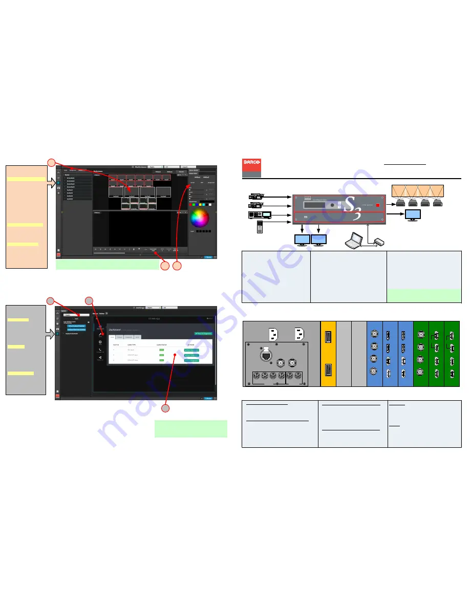
SETTINGS
MENU
S1: Options - From the
dropdown menu select
the desired language.
Click on the boxes to
select system wide
user preferences such
as Layer positioning.
S2: Tools - Allows
users to perform
Backup and Restore
operations or
download the latest
software from the
Barco website
S3 : Dashboard -
Provides status
information regarding
the cards and other
system diagnostic
information.
S
D
I
S
D
I
S
D
I
S
D
I
D
is
p
la
y
P
o
rt
D
is
p
la
y
P
o
rt
H
D
M
I
H
D
M
I
D
is
p
la
y
P
o
rt
D
is
p
la
y
P
o
rt
H
D
M
I
H
D
M
I
H
D
M
I
H
D
M
I
H
D
M
I
H
D
M
I
S
D
I
S
D
I
S
D
I
S
D
I
H
D
M
I
H
D
M
I
H
D
M
I
H
D
M
I
C
X
P
C
X
P
2
3
4
5
6
8
7
9
H
For release 2 only outputs 1 & 2 are active; Clocks will be available in
post software release 2.
M3
S2
S1
H
MULTIVIEWER (MVR)
MENU
M1: Select MVR Sources -
From the dropdown menus
select the Inputs,
Backgrounds and
Destinations you want to
view and drop them into a
Multiviewer Outputs.
Overlapping is not
allowed. A MVR source
can be used only once. A
maximum total of 64
windows can be used.
M2: Auto Layout Input -
Click on this button to
automatically place all
Inputs into the selected
output.
M3: Adjust Window -
Adjust the size, position
and the color parameters
associate with each
window. Repeat for all
Inputs and save.
VPU Cards
Dual Redundant Power Supplies
Genlock
In
Loop
1
Ethernet
1
2
3
4
1
2
S3D In
S3D Out
SEL
ESC
PWR