R 9849999
INSTALLATION MANUAL
Ceiling Mount for CLM series projector
Date
26/11/07
Rev:
00
Art.
No.:
R
59770182
Page 1: ...R 9849999 INSTALLATION MANUAL Ceiling Mount for CLM series projector Date 26 11 07 Rev 00 Art No R 59770182 ...
Page 2: ...thout notice Produced by BARCO NV Nov 2007 All rights reserved Trademarks are the rights of their respective owners BARCO n v Noordlaan 5 B 8520 Kuurne Belgium Tel 32 56 368211 Fax 32 56 351651 E mail sales bps barco com Visit Barco at the web http www barco com Printed in Belgium ...
Page 3: ...ith any other appliance projector may result in instability causing possible injury Do not modify and or replicate any component Barco n v uses specific materials and manufacturing processes in order to achieve part strength Consult Barco nv for assistance with custom applications Always follow Barco installation instructions Contact Barco n v if you should have any question regarding the safety o...
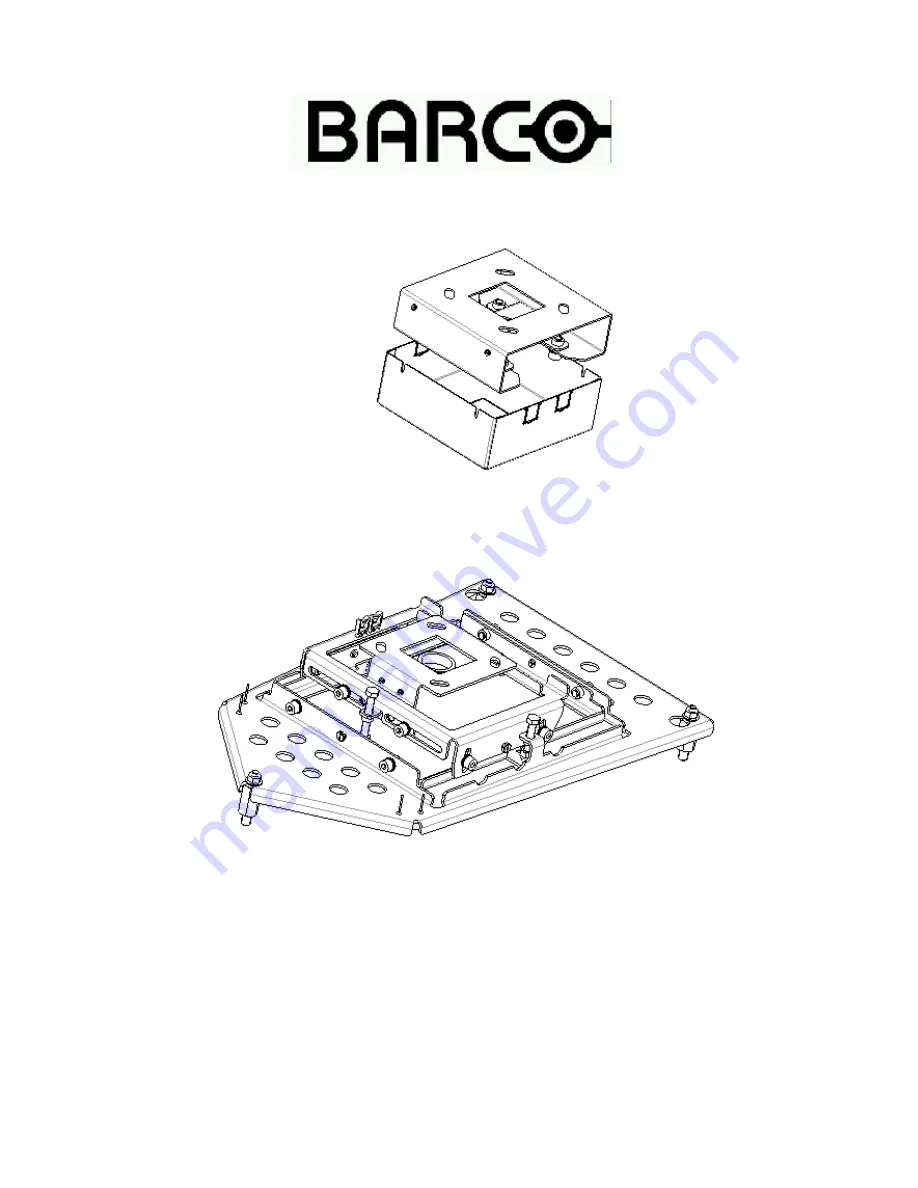
Page 4: ...o the ceiling Contents of the Kit Following items are included Kit R9849999 Ceiling mount Installation manual R59770182 Mounting bracket and Screws R835785 Qty 3 Nos and R 826743 qty 1 No Safety Chain set B361213 Qty 1 Nos A577535 qty 1 Nos A566050 qty 1 nos and B363509 qty 2 nos Cable cover assy Illustration of the ceiling mount R826743 R835786 R83578 ...
Page 5: ...mm 17 52 inch max length 810 mm 31 89 inch R9841261 long bar R822923 cable cover kit R984 min length 845mm 33 27 inch max length 1210 mm 47 64 inch I llustration of the Cable Cover Assy R826748 R826761 G229790 V3675126 R826749 R347968 7X Z348001 4X R826745 R347972 4 X Note The assembly is used only when ceiling mount is mounted along with IQ bar for hiding and guiding the cables ...
Page 6: ...ering the ceiling mount Mark the position on the ceiling hole Since the center of the lens does not coincide with the center of the projector the center of the lens has been marked on the ceiling mount Remark The horizontal shift of the ceiling mount allows to re enter the projector later on However centering decently the base plate insures a good horizontal shift margin afterwards ...
Page 7: ...Mounting the Assembly The fixation can be done with standard M8 bolt not supplied ...
Page 8: ...feet r852944 and x head M10 screw R852944 R852945 A566050 M10 SCREW FEET SUPPORT 2 Fix the Spacer M10 r835785 as shown below For alignment of the Centre distance between the spacers fix the ceiling mount and fix nut M8 B360623 Do not tight fully then tight the spacer M10 Remove the Ceiling mount and fix it on the Ceiling Washer Spacer M10 R835785 and Flange Nut M8 ...
Page 9: ...ate after the tightening of 3 M 8 flange Nuts b360623 Slide Lift 4 Route the Signal cables and Power cord into the cable saddles 5 Take care of the orientation of safety chain bracket 6 Fix the one end of safety chain into the projector s chain bracket with the help of the snap hook and the other end to the firm place in the Ceiling ...
Page 10: ...olts A and move the projector till the projector is aligned Tighten these 2 bolts to secure the position 2 Up down Tilt Loosen the 4 bolts B Adjust the up down tilt precisely by moving bolt C clockwise or anti clockwise Tighten the 4 bolts B to secure the position B 4no s 2 in opposite side Up down C A Axis 3 Rotate around central ...
Page 11: ...F vertical axis 5 E Rotate around Rotate around central Axis 3 G F ...
Page 12: ...just the projector clockwise or anti clockwise Tighten the 4 bolts E to secure the position 4 Rotate around central Horizontal axis Loosen the 4 bolts F Adjust the motion precisely by moving bolt G clockwise or anti clockwise Tighten the 4 bolts F to secure the position ...
Page 13: ...er part of the Bar Pass the cable cover into the upper part of the Bar 2 Slide the horizontal shift plate R 826743 into the lower part of the Bar Fix with 4 M8 bolt K 3 Slide the upper bar into the lower bar assembly Remount the 2 previously removed bolt J Adjust the height to minimum J K ...
Page 14: ... help of PVC tape arrange the connectors in series Pass the Signal cables and Power cord into cable guide R826761 b Pass the Signal cables into the IQ bar assembly from top side Take out the BNC connector in case of a 5 BNC cable one by one from bottom side ...
Page 15: ...g 2 M3 Screws L L The cable routing through IQ bar is complete Adjust the approximate height of the IQ bar and also adjust the length of the cable required at the projector side 5 Mount the Ceiling Bracket R 826748 on to the ceiling with standard M8 bolt not supplied with the Kit For marking of the ceiling holes refer the Installation manual of the Ceiling Mount of CV 120 R5973715 ...
Page 16: ... assembly Fix with 4 M8 bolt along with washer M M 7 Mount the Ceiling mount assembly on to the horizontal shift plate by twisting and then lifting up Fix the 2 M8 Bolt A A 8 Route the Power cord to the back and Signal cables to the front ...
Page 17: ...iling mount base as shown below Power cord other cables Cable Tie Cable Ties RGB cables Break the cable guide grooves on the cable cover as per the direction and location of the input cables and power cord at customer site room Lift the cable cover and fix with the help 4 M3 screws N Cable guide N Cable Guide Grooves ...
Page 18: ... cover and slide it down word Loosen the 4 bolts O Rotate adjust the projector clockwise or anti clockwise Tighten the 4 bolts O to secure the position Slide up the cable cover and fix 4 M3 screws N O O Rotate around l R83578 5 10 fix the one end of safety chain into the projector s Eye bolt and the other end to the firm place in the ceiling ...