background image

R5906897 /02

Prometheus III

82

7.1 Introduction

General

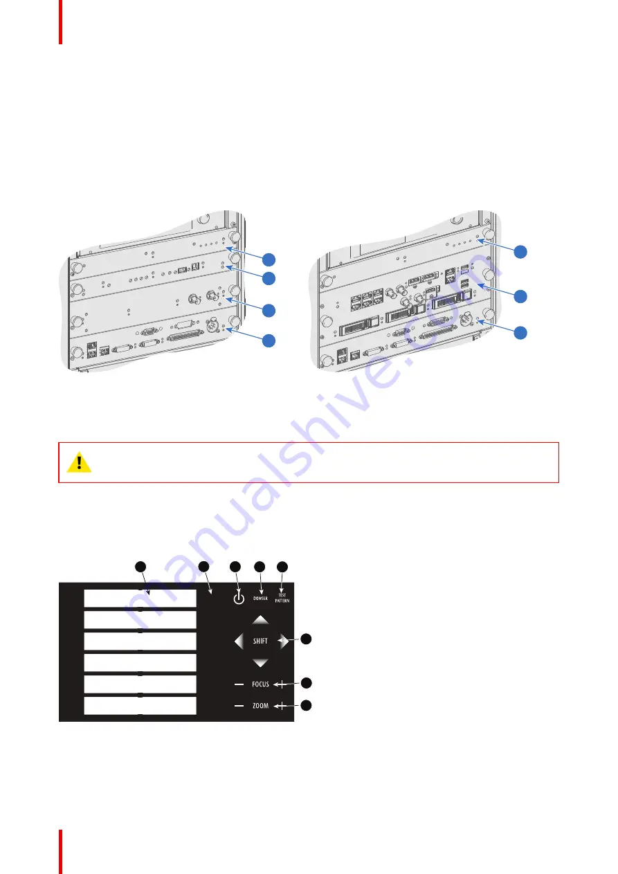
The Input & Communication side of the Prometheus III consists of a Local Keypad and a card cage with four
slots. The rear side of the projector is equipped with a tail light which reflects the status of the projector.

Depending on the projector configuration the projector card cage is equipped with an ICP or ICMP. See
illustration below. In case an ICP is installed then an IMB, IMS, or HDSDI input module can be optionally
inserted into the slot below the ICP. Note that all information about the ICMP is gathered into one separated
chapter called ICMP.

1

5

4

1

3

2

4

Image 7-1

1

Fan Control Board (FCB).

2

Integrated Cinema Processor (ICP).

3

Optional slot for either IMB, IMS or HD-SDI input
module.

4

Barco Cinema Controller.

5

Barco ICMP (inserted in ICP slot and optional
slot).

CAUTION:

A unit may only be removed from the card cage by qualified service personnel.

Removing one of the boards (except for the Cinema Controller) will result in an authorization
request upon starting.

7.2 Local keypad of the Prometheus III

Identification of the keys

1

2

3

4

5

6

2

1

3

4

5

6

7

8

Image 7-2: Local keypad

1

Marker area for macro name

2

Numeric keyboard

3

Standby key

4

Dowser open/close switch

Input & communication

Summary of Contents for Prometheus III

Page 1: ...ENABLING BRIGHT OUTCOMES Installation manual Prometheus III...

Page 2: ...Barco NV Beneluxpark 21 8500 Kortrijk Belgium www barco com en support www barco com Registered office Barco NV President Kennedypark 35 8500 Kortrijk Belgium www barco com en support www barco com...

Page 3: ...t this product may cause radio interference in which case the user may be required to take adequate measures BSMI Taiwan Class A statement Federal Communications Commission FCC Statement This equipmen...

Page 4: ...ng to compensation for direct or indirect damage and also damage attributed to the operation of software as well as to other services provided by Barco being a component of the system or independent s...

Page 5: ...e system 31 4 Physical installation projector 33 4 1 Positioning the Prometheus III at port window 34 4 2 Access to the power connection 36 4 3 Connecting the Prometheus III with the power net 37 4 4...

Page 6: ...ons 111 8 8 ICMP HDMI 1 4 specifications 114 8 9 ICMP status LEDs 117 8 10 ICMP HDD status LEDs 118 8 11 ICMP device certificate 119 8 12 ICMP configuration via Communicator 121 8 13 ICMP reset 122 8...

Page 7: ...4 4 Red on blue convergence 167 14 5 Green on blue convergence 168 15 Color calibration 171 15 1 Calibration process 172 15 2 White point calibration 172 15 3 Color gamut calibration 173 A Specificati...

Page 8: ...R5906897 02 Prometheus III 8...

Page 9: ...rification of the term Prometheus III used in this document When referring in this document to the term Prometheus III means that the content is applicable for following Barco products PROMETHEUS III...

Page 10: ...n the beam This risk is not specifically related to the characteristics of laser light but solely to the high thermal induced energy of the light source which is equivalent with lamp based systems The...

Page 11: ...stallation maintenance or service is for skilled persons only The requirements for a restricted access location an exclusion zone and a restriction zone Restricted access location To protect untrained...

Page 12: ...from the projector Do not allow anything to rest on the power cord Do not locate this projector where persons will walk on the cord Do not operate the projector with a damaged cord or if the projecto...

Page 13: ...ir effectiveness is impaired For example by cracks or deep scratches The associated Safety responsible of the unit must evaluate the setup before the unit may be started Never point or allow light to...

Page 14: ...nside the projector If this does happen switch off and remove all power from the projector Do not operate the projector again until it has been checked by qualified service personnel Do not block the...

Page 15: ...normal operation If the product has been dropped or the cabinet has been damaged If the product exhibits a distinct change in performance indicating a need for service Replacement parts When replaceme...

Page 16: ...ors performers or employees are permitted to stand or less than 1 0 meter SW lateral separation from any place where such persons are permitted to be In environments where unrestrained behavior is rea...

Page 17: ...sufficient separation height or by placing barriers The minimum separation height takes into account the surface upon which persons other than operator performers or employees are permitted to stand O...

Page 18: ...med Communication shall be maintained with other personnel assisting in surveillance of the LIP projection In the event of any unsafe condition immediately terminates or designate the termination of L...

Page 19: ...is mandatory to create a restricted zone within the beam areas closer than any HD In the enclosed projection area the combination of two restricted zones are relevant The restricted zone of the proje...

Page 20: ...ance 0 00 0 50 1 00 1 50 2 00 2 50 3 00 3 50 4 00 1 1 1 1 2 1 3 1 4 1 5 1 6 1 7 1 8 1 9 2 2 1 2 2 2 3 2 4 2 5 2 6 2 7 2 8 2 9 3 3 1 3 2 3 3 3 4 3 5 3 6 3 7 3 8 3 9 4 Hazard Distance HD m Throw Ra o TR...

Page 21: ...About Prometheus IIIs PROMETHEUS III Barco provides a guarantee relating to perfect manufacturing as part of the legally stipulated terms of guarantee Observing the specification mentioned in this cha...

Page 22: ...which are connected via hoses to external coolers Only coolers and hoses exclusively developed for this application and approved by Barco are allowed to be used Main Power requirements The Prometheus...

Page 23: ...offers a pedestal for the Prometheus III This universal pedestal allows a solid and easy setup of the projector The universal pedestal has a separate compartment to install the UPS unit for the Promet...

Page 24: ...Cooling housing Image 2 5 Hoses non contractual photo the length of the hoses may vary depending on the selected kit Image 2 6 Cooling filter Image 2 7 Cooler protection grid option for Stand alone c...

Page 25: ...rojector is surrounded with foam Once the projector has arrived at the installation site it needs to be removed from the carton box and wooden pallet in a safe manner without damaging the projector Af...

Page 26: ...Prometheus III 26 Image 2 9 Open banding 2 Open the box Take out the small box between the outer and inner box containing the manuals Remove the outer carton box Image 2 10 3 Remove the inner carton...

Page 27: ...ng the free end of the banding loop in the clip Take off the upper carton plate 1 Remove from the wooden pallet 2 1 2 Image 2 12 5 Take the projector from the wooden board by gripping the bottom of th...

Page 28: ...mmended to check if all following items where included One short power link cable mono phase in case no UPS is used Installed on projector A short information notice to inform the user that installati...

Page 29: ...parts installation of the projector and the installation of the cooler unit as top pack or stand alone pack Overview Installation process projector Installation process stand alone cooler Software up...

Page 30: ...f the Cooler See Installation process stand alone cooler page 30 8 Option Installation of the optional Communicator touch panel on the projector In both stand alone and top pack solutions it is possib...

Page 31: ...screen See Lens shift zoom focus page 69 See chapter Local keypad of the Prometheus III page 82 for detailed description of the Local Keypad buttons 3 Adjusting the light path Normally the lens holde...

Page 32: ...R5906897 02 Prometheus III 32 Installation process...

Page 33: ...Overview Positioning the Prometheus III at port window Access to the power connection Connecting the Prometheus III with the power net Power loop through to the projector electronics Connecting a UPS...

Page 34: ...e projector The universal pedestal has a separate compartment to install the UPS unit if available for the Prometheus III Futhermore the universal pedestal contains a standard 19 rack to build in the...

Page 35: ...placement Projector tilting In an ideal installation the Prometheus III lens surface is centered with and parallel to the screen This orientation helps to ensure optimized lens performances with minim...

Page 36: ...ilt maximum 15 forward and maximum 15 backwards This includes the tilt created by the projector feet and the tilt created by the pedestal Barco offers a pedestal for the Prometheus III projector This...

Page 37: ...le 4 3 Connecting the Prometheus III with the power net WARNING The total electrical installation should be protected by an appropriate rated and readily accessible disconnect switch circuit breakers...

Page 38: ...ugh the cable gland When using a flexible power cord make sure that each conductor end is provided with an end sleeve Fix the cable in the cable gland by securing ring 1 with an adjustable wrench 5 Co...

Page 39: ...ixation pins 3 while squeezing together and push it against the power plug Release the fixation spring 4 5 Connecting a UPS to the projector electronics WARNING Only use UPS units which are suitable f...

Page 40: ...r and push it against the power plug Release the fixation spring 4 Install on the power outlet the second fixation spring to prevent losing it 2 CAUTION The electrical connection with the UPS INLETsoc...

Page 41: ...e to refill the coolers or tubes on site Hence take care to protect the tubes and quick connectors Overview Supported mounting position Assembling the housing Mounting the housing on the frame Prepari...

Page 42: ...r is installed on a flat and stable surface in horizontal position Four feet correctly distributed 2 on each side allow stabilize the device The cooler could be tilted forward or backward but for secu...

Page 43: ...ll mounting When this option is chosen the cooler must be fixed on the wall in portrait mode or in landscape mode In portrait mode the cooler must be mounted with the cooling tubes up The other positi...

Page 44: ...authorized due to technical constraints Functioning and lifetime of internal pump could be impacted if the unit is installed in this position A B Image 5 6 A Landscape Mode with cooling tubes to the l...

Page 45: ...7 2 4 3 1 1 5 6 7 8 2 9 Image 5 8 This flat pack contains the following parts 1 Top plate 2 Side covers 3 M4 Hex Screws 4 M3 Hex Screws 5 Support for middle bracket 6 Side fixation 7 Position plate Ph...

Page 46: ...icative Don t hesitate to change the unit orientation to facilitate the mounting of parts By example it could be more easy to lay flat the front plate upon the table when you installing the both side...

Page 47: ...t screws M3 and tighten them fully until the brackets are pushed strongly against the ribs in the cover Note There may be paint job markings left on the internal side of the side covers e g in the gro...

Page 48: ...careful to orient the middle bracket like indicated in the drawing below the three holes at the below of the bracket must be placed at the opposite to the front plate Turn in a set screw M3 as indica...

Page 49: ...top plates and tighten them fully until the brackets are pushed strongly against the ribs in the cover and middle bracket Tip Put in place the screws without tightening them before slide the top plat...

Page 50: ...be mounted on the frame 5 3 Mounting the housing on the frame Required tools Allen key 3 mm How to mount 1 Place the housing on the cooler frame so that both positioning pins 1 on the housing match t...

Page 51: ...clamp a little bit in the housing Fixate the clamp fully so that it fits behind the rib on the housing Drive in a screw M3 to connect the clamp to the frame Repeat for the other side 3 Place the suppo...

Page 52: ...On the front side drive in the 2 screws M4 one at the left and one at right 1 Image 5 18 Note Only the hole referenced 1 must be used The other holes around are not used at this step of the procedure...

Page 53: ...a washer and a nut Continue with Installing the brackets on the cooler housing page 54 Wall mounting To install the standalone cooler in wall mounting mode follow this procedure 1 Place the stand alon...

Page 54: ...oling tubes will be facing upwards For landscape mode the U brackets are mounted on the left side cooling tubes will be facing to the left Continue with Installing the brackets on the cooler housing p...

Page 55: ...the frame Required parts Cooler housing already assembled Frame 5 Hex Screws M5x8 At this step of the procedure the frame is considered as being in its final position and already fixed if the wall mo...

Page 56: ...he housing when you look at the device on the side of the cooler inputs Image 5 24 3 Fixate the second U bracket to the frame with only one screws M5x8 as shown in the following drawing There is a spa...

Page 57: ...6 5 7 Insert the cooler units Required tools Flat screwdriver Before you start Check if the two indicated screws reference 1 are present If it is the case remove this screws The use of these screws ma...

Page 58: ...unit in the cooler housing Image 5 28 2 Slide the second cooler unit in the cooler housing 3 Fixate both units by closing the both captive screws 5 8 Mount the filters Required tools Flat screw driver...

Page 59: ...ver plate Image 5 29 2 Slide in a filter Look to the airflow sticker for the correct orientation Airflow is up Image 5 30 3 Place the cover plate back on its location and drive in both fixation screws...

Page 60: ...2f 2m Tube 4 2m 2f 1m 1f 1a 1b 2m 2f 2a 2b 1f 1m 2f 2m 1a 1b 2b 2a Image 5 31 Cabling tubing Cabling From projector connector plate To cooler XLR cable 1 1a 1a Control cable 1 1b 1b XLR cable 1 2f 2m...

Page 61: ...y slight impact to the cooling performance and hence the lifetime of the laser light source Required tools Flat screwdriver How to mount 1 Slide the grid reference 1 Image 5 32 in the fixation tabs re...

Page 62: ...R5906897 02 Prometheus III 62 Physical installation stand alone cooler...

Page 63: ...u can perform the Scheimpflug adjustment CAUTION Never transport the projector with a Lens mounted in the Lens Holder Always remove the Lens before transporting the projector Neglecting this can damag...

Page 64: ...0 3 35 X R9855947 HB 2 8 5 5 2 53 4 98 X R98565042 HC 1 13 1 72 X X R98562942 HC 1 35 1 86 X X R98562972 HC 1 46 2 10 X X R98563002 HC 1 65 2 60 X X R98563032 HC 2 00 3 35 X X R98565043 VHC 1 13 1 72...

Page 65: ...o fill in should be larger than the physical screen width due to the keystone distortion of the projected image How much larger depends on the amount of tilt Due to production tolerances the real dist...

Page 66: ...tion by moving the lens lock handle 1 towards the lens power supply socket 2 1 2 3 Image 6 3 Unlock lens holder 4 Ensure that the lens holder stands in the On Axis position horizontal and vertical mid...

Page 67: ...the Lens Holder 7 Secure the lens in the lens holder by sliding the lens lock handle into the locked position which is away from the lens power supply socket Ensure the lens touches the front plate of...

Page 68: ...the normal position will be lost A Spatial Color Calibration SCC has to be execute in case of a first install or in case a High Brightness lens is swapped with a High Contrast lens or vice versa See u...

Page 69: ...rized zoom focus functionality Maximum shift range The lens can be shifted with respect to the internal optics of the projector DMD which results in a shifted image on the screen Off Axis A 100 shift...

Page 70: ...quipped with a motorized zoom If yes use the and zoom keys on the local keypad to zoom in or out Image 6 11 If no use the zoom barrel on the lens to zoom in or out How to focus 1 Use the and focus key...

Page 71: ...ther from the DMD plane The closer the lens plane to the DMD plane the further the focus range Fr of the lens will be SCREEN DMD Lp1 Lp2 Fr1 Fr2 Image 6 13 Do not abuse the Back Focal Length adjustmen...

Page 72: ...Image 6 15 of the Lens Holder by 1 centimeter Use a 10mm nut driver for the lock nuts reference 21 Image 6 15 and use a 3mm Allen wrench for the set screws 11 11 21 Image 6 15 2 Fully loosen the Sche...

Page 73: ...the center of the projected image using the motorized focus control Local Keypad Ensure that the lens is zoomed for maximum image on the screen WIDE If yes nominal position is good for sharp focus in...

Page 74: ...qually in or out until the center of the projected image is sharp Note the same turning direction as in step 5 is applicable F 1 2 3 Image 6 21 8 Check if it is possible to focus the center of the pro...

Page 75: ...the lens holder to remove the tilt or swing between lens plane and DMD plane Lp3 Lp4 Image 6 22 Scheimpflug principle Scheimpflug principle The plane of sharp focus can be changed so that any plane c...

Page 76: ...a b c and d See Image 6 23 3 Loosen the 4 set screws A B C and D by 1 cm See Image 6 23 4 Fully loosen lock nut 4 See Image 6 23 5 Optimize the focus of the projected image as follows 1 Turn the Sche...

Page 77: ...III 77 1 F Image 6 26 Left bottom focusing 7 Sharpen bottom right corner of the screen by adjusting nut 2 2 F Image 6 27 Right bottom focusing 8 Sharpen top right corner of the screen by adjusting nu...

Page 78: ...rming the procedure for Scheimpflug adjustment or Back Focal Length adjustment the Lens Holder front plate must be secured in such a way that it doesn t disturb the result of the adjustment Required t...

Page 79: ...heimpflug adjustment nut at the lower left of the Lens Holder reference 4 Image 6 31 against the Lens Holder front plate without disturbing the projected image 6 Turn in the set screw at the lower lef...

Page 80: ...R5906897 02 Prometheus III 80 Lenses lens holder...

Page 81: ...the Prometheus III Integrated Cinema Processor ICP HD SDI Input Module optional Quad 3G SDI Input Module optional Integrated Media Block Server optional Cinema Controller of the Prometheus III R590689...

Page 82: ...l information about the ICMP is gathered into one separated chapter called ICMP 1 5 4 1 3 2 4 Image 7 1 1 Fan Control Board FCB 2 Integrated Cinema Processor ICP 3 Optional slot for either IMB IMS or...

Page 83: ...ve for about 5 minutes The speed of the other fans is reduced The backlight color of the standby key remains red in standby mode and changes to green in operation mode Dowser key The dowser key 4 open...

Page 84: ...red unable to configure the FPGA yellow FPGA is loaded with the Boot application ICP functions Stores all projector files When board is replaced clone package must be reloaded Stores and generates tes...

Page 85: ...m allowed 2 SMPTE 292 424 input port B maximum cable length of 30 m allowed SMPTE Society of Motion Picture and Television Engineers A global organization based in the United States that sets standar...

Page 86: ...Z RGB Progressive field bit normal Progressive field bit inverted Progressive SF 2nd field dominant Progressive SF 1st field dominant Source 2K 3D General settings Advanced settings Port Port type Mod...

Page 87: ...ft right eye 4 4 4 10 bits color Progressive RGB 3G Level A Interleaved Single Dual separate left right eye 3G Level B Interleaved Single Dual separate left right eye 4 4 4 12 bits color Progressive X...

Page 88: ...Source 3D HFR General settings Advanced settings Port Port type Mode Scan type Color space Pixel mapping Calibration A B 3GSDI 3D HFR 4 2 2 10 bits color Progressive YCbCr 3G Level A Interleaved Singl...

Page 89: ...B HD SDI Single link 4 2 2 10 bits color Progressive YCbCr HD SDI Single link Single Progressive field bit normal Progressive field bit inverted Progressive SF 2nd field dominant Progressive SF 1st f...

Page 90: ...2 2 10 bits color Progressive YCbCr HD SDI Single link Single Progressive field bit normal Progressive field bit inverted Progressive SF 2nd field dominant Progressive SF 1st field dominant 3G SDI lin...

Page 91: ...eparate left right eye Progressive SF 1st field dominant YCbCr HD SDI Interleaved Single Dual separate left right eye Progressive SF 2nd field dominant YCbCr HD SDI Interleaved Single Dual separate le...

Page 92: ...Progressive SF 2nd field dominant 3G SDI HFR 4 2 2 12 bits color Progressive YCbCr 3G Level A Interleaved Single 3G Level B Interleaved 4 4 4 10 bits color Progressive RGB 3G Level A Interleaved Sing...

Page 93: ...t YCbCr 3G Level A Quad Link Single 3G Level B Quad Link Progressive SF 2nd field dominant YCbCr 3G Level A Quad Link Single 3G Level B Quad Link 4 4 4 10 bits color Progressive RGB 3G Level A Quad Li...

Page 94: ...the projector configuration the projector card cage is either equipped with an ICP or ICMP In case an ICP is installed then an IMB IMS or HDSDI input module can be optionally inserted into the slot be...

Page 95: ...et port reference 2 Image 7 9 to connect the network which contains the DHCP server The Prometheus III can be connected to a WAN Wide area network reference 2 Image 7 9 Once connected to the WAN users...

Page 96: ...ed The standard specifies component connection standards with regard to computer interface It is also called RS 232 C which is the third version of the RS 232 standard and is functionally identical to...

Page 97: ...60 Progressive RGB 4 4 4 8 bit Single DVI 1920x1080i 50 60 Interlaced RGB 4 4 4 8 bit Twin DVI ACS 2048x1080 50 59 94 Progressive RGB 4 4 4 10 bit Twin DVI ACS 2048x1080 50 59 94 Progressive RGB 4 4 4...

Page 98: ...R5906897 02 Prometheus III 98 Input communication...

Page 99: ...Image 8 1 Overview ICMP introduction ICMP HDD ICMP communication ports ICMP source input ports ICMP DisplayPort specifications ICMP SDI specifications ICMP HDMI 2 0 specifications ICMP HDMI 1 4 speci...

Page 100: ...R5906897 02 Prometheus III 100 Installing a HDD into the ICMP ICMP...

Page 101: ...The standard Integrated Cinema Processor functionality from Texas Instruments is fully integrated into the ICMP So the ICMP replaces the ICP board as well 2 1 Image 8 2 1 ICMP 2 HDDs for ICMP As an i...

Page 102: ...series C series BLP series or CLP series projector 1 2 Image 8 5 8 2 ICMP HDD About ICMP HDD The three HDDs local storage in the ICMP are set up in a RAID 5 configuration This storage technique that...

Page 103: ...ICMP or to reuse a complete set of disks coming from another projector with ICMP It is sufficient to insert the three HDDs from a valid RAID array and let the system explore the new RAID The mounting...

Page 104: ...ide for further information 3 GPI 1 4 5 8 These RJ45 connectors can be used to receive trigger signals from other devices The mapping of the General Purpose Input GPI on each input Cues is configured...

Page 105: ...imum signaling rate of 480 Mbit s effective throughput up to 35 MB s or 280 Mbit s in addition to the USB 1 x Full Speed signaling rate of 12 Mbit s 16 USB 2 0 connectors are usually colored black USB...

Page 106: ...a form of digital copy protection developed by Intel Corporation to prevent copying of digital audio and video content as it travels across DisplayPort Digital Visual Interface DVI High Definition Mul...

Page 107: ...88 2 kHz 96 kHz 5 1 format LPCM 24 bits 48 kHz 7 1 format LPCM 20 bits 48 kHz Notes DisplayMode Single is applicable to both DisplayPort A and DisplayPort B input separately DisplayMode A B inputs Dis...

Page 108: ...a rates to 2 97 Gbps using the same 75 ohm coaxial cable This new standard also called 3 Gbps 3G SDI enables higher resolution of picture quality required for 1080p and digital cinema SDI terminology...

Page 109: ...ther SMPTE 292M STANDARD 1 485 Gb s HD SDI SIGNALS Standard HD SDI SMPTE 292M formats SMPTE Standard Source Resolution Frame Rate Display Rate Scan Type SMPTE 296M 1280 x 720 23 976 24 25 29 970 30 50...

Page 110: ...YZ 4 4 4 10 or 12 Bit Standard HD SDI 2 SMPTE 292M formats3 SMPTE Standard Source Resolution Frame Rate Display Rate Scan Type SMPTE 292M SMPTE 428 8 1920 x 1080 2048 x 1080 23 976 24 25 29 97 30 47 9...

Page 111: ...Z 4 4 4 12 Bit Dual Stream 3G HD SDI SMPTE 425 formats SMPTE Standard Source Resolution Frame Rate Display Rate Scan Type SMPTE 292M SMPTE 428 9 1920 x 1080 2048 x 1080 23 976 24 25 29 970 30 47 952 4...

Page 112: ...e there are quality differences The high speed cables would be preferred over the standard speed cables They usually work at higher cable lengths than the standard speed ones The Premium Certified HDM...

Page 113: ...Supported 3D Frame Packing Formats Format Frame Rate Color coding Bit depth 1920x1080 2048x1080 23 976 24 25 29 97 30 RGB YCbCr 4 4 4 YCbCr 4 2 2 8 10 12 1920x1080 2048x1080 50 59 94 60 RGB YCbCr 4 4...

Page 114: ...icant bits of port B HDMI 2 0 Supported Passive 3D Formats 3D formats only Format Frame Rate Color coding Bit depth 1920x1080 2048x1080 24 30 RGB YCbCr 4 4 4 YCbCr 4 2 2 8 10 12 1920x1080 2048x1080 60...

Page 115: ...8 10 12 720x576 50 RGB YCbCr 4 4 4 YCbCr 4 2 2 8 10 12 1280x720 23 976 24 25 29 97 30 50 59 94 60 100 119 88 120 RGB YCbCr 4 4 4 YCbCr 4 2 2 8 10 12 1680x720 23 976 24 25 29 97 30 50 59 94 60 100 119...

Page 116: ...4 YCbCr 4 2 2 8 10 12 HDMI 1 4 Supported 2D Interlaced Formats Format Frame Rate Color coding Bit depth 720x576 25 50 100 1920x1080 25 29 97 30 50 59 94 60 HDMI 1 4 Supported 3D Frame Packing Formats...

Page 117: ...READY LEDs PWR ERROR READY ICMP Status Off Off Turned off Red Off Board reset or FIPS error Blinking Green Off Boot loader Blinking Green Blinking Orange Operating System start up Blinking Green Oran...

Page 118: ...2 Replace the defect HDD with approved model of the same storage capacity See procedure Removing a HDD from the ICMP page 124 and Installing a HDD into the ICMP page 125 Ensure to insert the HDD firm...

Page 119: ...ure Removing a HDD from the ICMP page 124 and Installing a HDD into the ICMP page 125 Ensure to insert the HDDs firmly 3 If problem remains try RAID Initialize See user guide of the Communicator Note...

Page 120: ...tities Integrators Service Providers interacting with Exhibitors regional authorities and Support Public Key Infrastructure PKI PKI is a framework for creating a secure method for exchanging informati...

Page 121: ...pecifications for an open architecture for digital cinema that ensures a uniform and high level of technical performance reliability and quality control Note that the DCI specification is not a standa...

Page 122: ...on the front panel of the ICMP Not recommended use only when all other reset possibilities are exhausted How to reset the ICMP 1 Click on the ICMP reset button in the GUI of the Web Commander or Click...

Page 123: ...e of the ICMP with a smartphone It s recommended to use a smartphone with auto focus The QR reader will automatically redirect to the ICMP certificate download page on the web server Note Instead of d...

Page 124: ...om the ICMP In case the ICMP has to be returned to factory e g for repair the non defective HDDs should be removed and kept How to remove a HDD 1 Switch off the projector 2 Moving the latch towards th...

Page 125: ...P HDD set have the same storage capacity See label on top of the HDD to know the storage capacity How to install a HDD 1 Ensure that the projector is switched off 2 Prepare the HDD for insertion by mo...

Page 126: ...ecovery process The red LED of the HDD which has to be rebuilt is blinking This process takes about 200 GB per hour Once the RAID is completed the red LED turns off CAUTION It s strongly recommended t...

Page 127: ...127 Overview Introduction Installation of the touch panel interface R5906897 02 Prometheus III Communicator Touch Panel 9...

Page 128: ...m of the swivel arm allows an instant fixation of the touch panel interface in any position The touch panel interface can also be installed further away from the Prometheus III For that you can use a...

Page 129: ...erface 1 Assemble the mounting plate and the swivel arm together as illustrated First place the nut N upon the rod of the mounting plate then add the lock washer L then fasten the mounting plate and t...

Page 130: ...swivel arm and fasten the two wing nuts W as illustrated W Image 9 5 Mount touch panel 4 Connect the circular plug of the multi cable with the circular socket at the rear side of the Prometheus III I...

Page 131: ...R5906897 02 Prometheus III 131 6 Connect the DC plug the RJ45 Ethernet plug and the D SUB plug into their respective sockets on the touch panel interface Image 9 7 Connections Communicator Touch Panel...

Page 132: ...R5906897 02 Prometheus III 132 Communicator Touch Panel...

Page 133: ...rometheus III These procedures enumerate all the important points which have to be checked prior to switching ON the projector This is to ensure a safe start up of the projector Overview Switching ON...

Page 134: ...le the projector is switched OFF When 1 is visible the projector is switched ON 8 During this step some checking procedures are executed on the laser unit The laser is OFF and the dowser closed No int...

Page 135: ...herwise stated Overview Removal of the light source cover Removal of the rear cover Removal of the input cover Removal of the front cover Removal of the side cover Installation of the front cover Inst...

Page 136: ...heus III 136 Location of the covers 1 2 3 4 5 Image 11 1 1 Light source cover 2 Input cover 3 Front cover 4 Side cover 5 Rear cover All cover can be individually removed Removal and installation of th...

Page 137: ...th captive screws on top of the lamp cover Image 11 2 Light Source cover loosening screws 2 Push both lock to each other to release the locks and pull at the same time the bottom side of the cover awa...

Page 138: ...st at the bottom of the rear cover using a flat screw driver 1 1 1 2 2 Image 11 5 Rear housing removal 2 Remove the rear cover of the projector doing the following 1 gently pull out the top covers of...

Page 139: ...r fixation 2 Remove the input cover as follow 1 Pull the bottom side of the cover to you until the cover is unlocked 2 Slide the full cover away from the projector Image 11 7 Input cover removal 11 4...

Page 140: ...Release the captive screw at the middle bottom of the front cover 4 Remove the front cover as follow 1 standing in front of the projector pull the top side of the cover to you until it is unlocked 2 s...

Page 141: ...Release both captive screws on top of the side cover Image 11 10 Captive screws 2 Push both lock to each other to release the locks and pull at the same time the bottom side of the cover away form the...

Page 142: ...next steps to install the front cover 1 Hook the bottom side of the cover to the projector 2 Gently push the top side of the cover into position 3 Ensure that the locking studs click into their recei...

Page 143: ...front cover 4 Reinstall the rubber dust ring around the lens holder 11 7 Installation of the input cover Required tools Flat screwdriver How to install 1 Place the top side of the cover on its place...

Page 144: ...h the bottom side until the locking studs click in the receivers Image 11 16 Secure input cover 3 Secure the cover by fastening the captive screw 11 8 Installation of the light source cover Required t...

Page 145: ...s 2 Secure the cover by fasting both captive screws Image 11 18 Secure light source cover 11 9 Installation of the rear cover Required tools Flat screwdriver How to install 1 Install the rear cover of...

Page 146: ...ow to install 1 Place the top of the side cover on its place Image 11 20 Mounting the side cover Close the cover as follow 1 Gently move the bottom side of the cover towards the projector 2 Push both...

Page 147: ...R5906897 02 Prometheus III 147 Image 11 21 Lock side cover 2 Secure the cover by fasting both captive screws Image 11 22 Lock side cover Removal and installation of the projector covers...

Page 148: ...R5906897 02 Prometheus III 148 Removal and installation of the projector covers...

Page 149: ...4 yearly maintenance actions not included in this manual which must be done by certified service personnel who are familiar with potential hazards of the product and all product safety checks Contact...

Page 150: ...ed filters immediately See procedures Remove and clean the front dust filter page 154 Remove and clean both bottom dust filters page 155 To speed up drying allow the filter s to dry at 50 C max in a w...

Page 151: ...st filters page 156 To speed up drying allow the filter s to dry at 50 C max in a well ventilated room 2 Clean the back side air inlet vents Use a vacuum cleaner 3 Clean the housing of your projector...

Page 152: ...R5906897 02 Prometheus III 152 Preventative maintenance actions...

Page 153: ...the cooler dust filters Vacuum cleaning of the dust filters Washing and drying the dust filters Cleaning the lens Cleaning the exterior of the projector Check cooling liquid level Cooling liquid refil...

Page 154: ...the dust filter 1 Remove most contamination gently with a vacuum cleaner in an other room or outside 2 Blow remaining dust away with clean without oil lubricant compressed air in an other room or out...

Page 155: ...ly in 3 Reinstall the input cover 13 2 Remove and clean both bottom dust filters How to remove 1 Remove the side cover 2 Slide out the bottom front dust filter Image 13 3 Bottom front dust filter 3 Sl...

Page 156: ...ntil they click into position 3 Reinstall the side cover 13 3 Check the cooler dust filters How to check 1 Remove both fixation screws captive screws and take off the cover plate 1 Image 13 5 2 Slide...

Page 157: ...ese must be washed See cleaning procedure Washing and drying the dust filters page 157 Grease on the filter can build up after several months in an environment contaminated with greasy air Note that a...

Page 158: ...dissolved after 1 hour 3 If the dust filter is still clogged repeat this procedure from step 1 4 Rinse the dust filters with clean water to flush all grease residue away 5 Shake out all excess liquid...

Page 159: ...dry one If smears occur when cleaning lenses replace the cloth Smears are the first indication of a dirty cloth 13 7 Cleaning the exterior of the projector How to clean the exterior of the projector 1...

Page 160: ...in the cooling system prior starting the refill procedure If you cannot see the level open the filler cap and shine a torch into the reservoir 13 9 Cooling liquid refill WARNING This procedure may on...

Page 161: ...3 10 Authorization to clear security warning on the projector When is an authorization required to clear the security warning If a module has been removed or if the sealed compartment has been opened...

Page 162: ...t of the numeric keys 1 to 6 changes back to blue In case of an incorrect code entry the color of the backlight of the numeric keys changes to red for 1 second and then back to blue In case of a corre...

Page 163: ...are the projector for convergence adjustment and how to adjust the convergence Overview Open the sealed compartment Close the sealed compartment Convergence controls Red on blue convergence Green on b...

Page 164: ...is procedure may only be done by a qualified and trained service technician Required tools 3 mm Allen wrench How to open the sealed compartment 1 Remove both hexagon head cap screws 1 1 Image 14 1 Sea...

Page 165: ...on to clear security warning on the projector 14 2 Close the sealed compartment Required tools 3 mm Allen wrench How to close the sealed compartment 1 Hook the cover plate on the studs 2 Image 14 3 Se...

Page 166: ...to the top Z rotation Tilting of the X and Y axes in their plane is clockwise rotation 1 2 3 4 5 6 these are the 6 adjustments available as they appear on the standard convergence adjustment screen Co...

Page 167: ...adjust the convergence Take Care In rare cases it can happen that the nominal dmd position falls within a dead zone where the mechanism changes from a pushing to a pulling function This dead zone is d...

Page 168: ...rotation is required 2 may also be turned in the opposite direction Slight corrections to Y may be required after rotation 6 For anti clockwise rotations of RED turning 1 clockwise would generally suf...

Page 169: ...r rotation 4 For anti clockwise rotations of GREEN turning 5 clockwise would generally suffice If much rotation is required 4 may also be turned in the opposite direction Slight corrections to Y may b...

Page 170: ...R5906897 02 Prometheus III 170 Convergence...

Page 171: ...tailed menu navigation instructions The first chapter describes the complete calibration process in chronological order Color calibration should be executed during the installation of the projector an...

Page 172: ...important that the MCGD file s and matching TCGD file s are activated after that the INPUT file and PCF file are activated For that it is recommended to create a macro where the files are loaded one b...

Page 173: ...ied This color space is the Target Color Gamut Data TCGD All movie content operates under that gamut To ensure that in the cinema theater the film is projected within the same color space as intended...

Page 174: ...If not see White point calibration page 172 2 Setup the ambient light conditions as it should be during the play out of the movie e g only the stairs and emergency exit lighting is switched on Note In...

Page 175: ...calibration Select target colors For detailed instructions see user guide of the Communicator 6 In addition you can check if the corrected colors comply Use therefore the Communicator Go to Installat...

Page 176: ...R5906897 02 Prometheus III 176 Color calibration...

Page 177: ...ions of the Prometheus III Specifications of the ICMP Dimensions of the Prometheus III Dimensions of the universal pedestal Projector air inlets and outlets Technical Regulations R5906897 02 Prometheu...

Page 178: ...rtical lens shift up to 15 horizontal lens shift Motorized zoom focus shutter and lens shift Optical dowser Yes Color correction P7 Color gamut Wider than DCI P3 Image processing Alchemy Integrated Ci...

Page 179: ...emperature 10 to 35 C Max sea Level Operational humidity 85 Max projector and cooler BTU per hour 10 796 BTU h Airflow requirements Air Inlet from Rear w Feet Down Front Exhaust from Rear w Feet Down...

Page 180: ...captioning devices Support for SMPTE 430 10 4K 24fps is standard For 4K 60 fps 4K 3D on ICMP upgrade modules a license is required Newly built 4K Barco Alchemy projectors have the license standard in...

Page 181: ...MI2 0 HDR Licence for Dual Projector TMS support Barco Alchemy is supported by the following Theater Management System TMS brands AAM Screenwriter Ymagis Melody CFG Barco Unique RosettaBridge ADDE Cin...

Page 182: ...7 02 Prometheus III 182 A 3 Dimensions of the Prometheus III Dimensions 754 572 675 37 5 41 5 456 219 381 5 604 min 31 74 721 504 859 188 82 454 1129 Image A 1 Dimensions given in millimeters Specific...

Page 183: ...R5906897 02 Prometheus III 183 A 4 Dimensions of the universal pedestal Dimensions 566 7 866 8 876 3 Image A 2 Dimensions given in millimeters Specifications...

Page 184: ...air inlets and outlets Air inlets and outlets Image A 3 A 6 Technical Regulations Certificates Image A 4 EAC mark 10 Image A 5 Rohs Image A 6 CE mark Image A 7 ETL mark Image A 8 CCC mark Image A 9 C...

Page 185: ...ut General Purpose Inputs Outputs GPIO Pin configurations of the communication ports Pin configurations of the ICMP communication ports Pin configurations of the inputs R5906897 02 Prometheus III Pin...

Page 186: ...In N 4 7V Input to projector Internal projector 1k1 5V to 18V Image B 1 Cables When long cable connections are required the use of shielded cables with twisted pairs is recommended One twisted pair is...

Page 187: ...tate changes to the default state The default GPO state depends on the external system connected with the GPO port pull up or pull down circuitry GPIO and projector Sleep mode In case the projector is...

Page 188: ...e N 10 GPOUT 2 P reserved 29 GPOUT 2 N reserved 11 GPOUT 3 P reserved 30 GPOUT 3 N reserved 12 GPOUT 4 P 31 GPOUT 4 N 13 GPOUT 5 P 32 GPOUT 5 N 14 GPOUT 6 P 33 GPOUT 6 N 15 GPOUT 7 P 34 GPOUT 7 N 16 G...

Page 189: ...32 TX 13 CONN_3D MODE 6 CONN_3D_MODE 14 CONN_SYNC 7 CONN_SYNC 15 8 3D Input Reference B 3 Pin configurations of the ICMP communication ports RJ 45 pin configuration P1 P8 Image B 3 Audio Channels AUDI...

Page 190: ...EXT_GPOUT_2_N 4 EXT_GPOUT_3_P 5 EXT_GPOUT_3_N 6 EXT_GPOUT_4_P 7 EXT_GPOUT_4_N 8 GPO 5 8 Definition RJ 45 pin EXT_GPOUT_5_P 1 EXT_GPOUT_5_N 2 EXT_GPOUT_6_P 3 EXT_GPOUT_6_N 4 EXT_GPOUT_7_P 5 EXT_GPOUT_7...

Page 191: ...and green Hold a cable as if to plug it into a wall jack the locking tab down contacts facing you The contacts are numbered 1 8 from left to right Here s what you will see RJ 45 Pin Number Left Right...

Page 192: ...inputs DVI D DVI IN A B 1 RX2 7 DDC Data 13 nc 19 RX0 Shield 2 RX2 8 nc 14 5V 20 nc 3 RX2 Shield 9 RX1 15 GND 21 nc 4 nc 10 RX1 16 Hot Plug Detect 22 TMDS Clock Shield 5 nc 11 RX1 Shield 17 RX0 23 TMD...

Page 193: ...isposal information China RoHS compliance Taiwan RoHS compliance Turkey RoHS compliance Hazards Contact information Production address Download Product Manual R5906897 02 Prometheus III Environmental...

Page 194: ...ese chemical symbols will appear below the crossed out wheeled bin symbol By participating in separate collection of batteries you will help to ensure proper disposal and to prevent potential negative...

Page 195: ...equirement in GB T 26572 X GB T 26572 X Indicates that this toxic or hazardous substance contained in at least one of the homogeneous materials used for this part is above the limit requirement in GB...

Page 196: ...O O O Internal wiring O O O O O Lens holder O O O O O Optical lenses O O O O O Laser O O O O O Nuts bolts screws washers fasteners O O O O O Power Supply Unit O O O O O Fan O O O O O Pump O O O O O 1...

Page 197: ...information Barco contact information Registered office address President Kennedypark 35 8500 Kortrijk Belgium Contact address Beneluxpark 21 8500 Kortrijk Belgium Importers contact information To fin...

Page 198: ...Manual Product manuals and documentation are available online at www barco com td Registration may be required follow the instructions given on the website IMPORTANT Read Installation Instructions bef...

Page 199: ...R5906897 02 Prometheus III 199 Environmental Information...

Page 200: ...Registered office Barco NV President Kennedypark 35 8500 Kortrijk Belgium Barco NV Beneluxpark 21 8500 Kortrijk Belgium www barco com R5906897 02 2019 02 07...

Reviews: