background image

3. Physical installation of a MiPIX display system

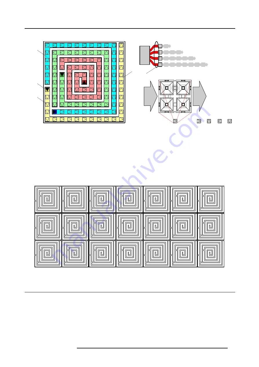
Tile with 11 x 11 MiPIX blocks.

A

1

2

3

4

1

2

3

4

IN

OUT

0

1

2

3

90º

180º

270º

B

C

D

MiPIX

controller

D

1

2

3

4

Image 3-3
Legend:

A

Chain of MiPIX blocks.

B

Input (connection with controller) of the chain.

C

Represent a pixel block with a certain orientation (0º, 90º, 180º or 270º).

D

Output port number of the MiPIX control unit to which this chain is connected.

The tile configuration consist of four chains of MiPIX blocks placed in a spiral. Starting from the middle of the tile, coming out counter
clockwise. The first three chains contains 128 pixels or 32 MiPIX-20 blocks. The last chain contains 100 pixels or 25 MiPIX-20
blocks. The input (connection with the controller) of the chain is fixed as illustrated above. Note that the physical orientation of the
MiPIX-20 blocks for tile configuration must correspond with the above scheme.

The tile configuration is most suitable when you want to create your own MiPIX tiles. Using this tile configuration on a frame with a
square shape support grid and with on the back of the frame the MiPIX control unit mounted, gives you a customized LED tile. This
tile can easily be used to create very large MiPIX displays. See example below.

11 x 11

11 x 11

11 x 11

11 x 11

11 x 11

11 x 11

11 x 11

11 x 11

11 x 11

11 x 11

11 x 11

11 x 11

11 x 11

11 x 11

11 x 11

11 x 11

11 x 11

11 x 11

11 x 11

11 x 11

11 x 11

Image 3-4

3.3 Attach MiPIX-20 blocks to the support grid

What has to be done ?

The MiPIX-20 blocks has to be inserted in the support grid and connected with each other according a supported configuration
scheme. For more information on physical positions of pixel blocks, in relation to each other, and electrical connections, see Con-
figuration schemes of MiPIX blocks, page 15.

There are two methods of installing MiPIX-20 blocks. The first method is to snap the MiPIX-20 blocks into the support grid first and
then plug in the inter-block cable between the MiPIX-20 blocks. The second method is the other way around. First connect the
inter-block cable with the MiPIX-20 blocks and then snap in the MiPIX-20 blocks. The second method can be very handy in case
there is insufficient space behind the support grid.

R5976717 MIPIX-20 07042004

17

Summary of Contents for MiPIX-20

Page 1: ...MEDIA EVENTS MIPIX 20 INSTALLATION MANUAL 07042004 R5976717 02...

Page 2: ...Barco nv Events Noordlaan 5 B 8520 Kuurne Phone 32 56 36 89 70 Fax 32 56 36 88 24 E mail events barco com Visit us at the web www barco com Printed in Belgium...

Page 3: ...being a component of the system or independent service will be deemed invalid provided the damage is not proven to be attributed to the absence of properties guaranteed in writing or due to the intent...

Page 4: ......

Page 5: ...11 2 5 MiPIX prime cable extension kit 11 2 5 1 Prime cable extension kit introduction 11 2 5 2 MiPIX cable extension transmitter and receiver specifications 12 2 5 3 MiPIX cable extension transmitte...

Page 6: ...Table of contents 2 R5976717 MIPIX 20 07042004...

Page 7: ...h may cause a decrease in load capability the part must be removed for service or replaced immediately Under no circumstances are Barco parts repairable by anyone other than Barco 1 2 Important safety...

Page 8: ...ainst risk of fire by overloading of power cables MAXIMUM 10 MiPIX controller units are allowed per power source cable The power source cable should be protected by a circuit breaker or fuses rated 16...

Page 9: ...xel blocks Sources MiPIX controller MiPIX controller Image 2 1 2 2 MiPIX 20 block 2 2 1 MiPIX 20 introduction Introduction The MiPIX 20 block is a modular intelligent LED pixel block which measures on...

Page 10: ...one inter block cable of 10 cm 50 pack R98523020 MiPIX 20 block plus one inter block cable of 10 cm 200 pack R9852290 Housing for the MiPIX 20 block 50 pack image 2 5 Image 2 2 Image 2 3 Image 2 4 Ima...

Page 11: ...Dimensions given in millimeters 2 3 MiPIX control unit 2 3 1 MiPIX control unit introduction Introduction The MiPIX control unit has a built in re sync unit which receives data from the digitizer or f...

Page 12: ...ble image 2 9 R9852135 Power split cable 5 pack R98521310 Power split cable 10 pack R9851980 MDR cable of 5 meter used for connections between control units image 2 10 R9851980 MDR cable of 5 meter us...

Page 13: ...ts 4 ports 128 pixels per port equals 32 MiPIX 20 blocks Maximum power consumption 206 watt Weight 2 22 kg Dimensions 424 2 x 80 x 123 mm W x H x D Operating temperature 0 to 40 C 32 to 104 F Storage...

Page 14: ...ync unit can bridge a distances of five 5 meter Maximum three 3 MiPIX stand alone re sync units are allowed between two 2 MiPIX control units Order info Article No Description Image R9851990 MiPIX sta...

Page 15: ...ist in a transmitter unit a receiver unit and a MDR cable of 10 meter The extension kit is placed between the output port of the control unit and the first pixel block MiPIX controller TX RX TX RX Ima...

Page 16: ...eter Maximum number of TX RX sets per output port of the MiPIX control unit Maximum two 2 TX RX sets per output port of the MiPIX control unit Maximum eight 8 TX RX sets per controller unit Weight tra...

Page 17: ...r the snap fit feature of a MiPIX 20 block It s recommended that the grid spacing is a multiple of the MiPIX 20 pixel pitch Two or more times 20 3636 mm This is important to get a good impression of t...

Page 18: ...unction with the digitizer and display this can be used when connected to the digitizer through a serial RS232 connection Refer to the manual of the digitizer for more information about the digitizer...

Page 19: ...et has to be installed on a local PC see manual of the control software for more information 7 Initialize and start up the MiPIX display Energize the power box es and the digitizer s then start up the...

Page 20: ...n with controller of a linear chain can be left or right for horizontal configurations either top or bottom for vertical configurations The input location can be different among the chains in the same...

Page 21: ...uare shape support grid and with on the back of the frame the MiPIX control unit mounted gives you a customized LED tile This tile can easily be used to create very large MiPIX displays See example be...

Page 22: ...to fasten a wire unit with an eyelid Use a M3 x 10 bolt Warning This individual ground connection per pixel block is necessary to comply with the CE and FCC regulations Caution Using a bolt longer th...

Page 23: ...pport grid as soon as the pixel block snaps in 6 Attach the next pixel block to the support frame as illustrated Ensure that the pixel block is correctly oriented image 3 7 7 Repeat from step 3 until...

Page 24: ...tension kit to realize the connection see Using the MiPIX prime cable extension kit page 21 3 Repeat step 1 and 2 until all MiPIX control units are installed 4 Realize the data cabling between the MiP...

Page 25: ...X control unit image 3 12 Tip The housing of the MiPIX control unit is equipped with mounting holes for the transmitter unit If you use those mounting holes use M3 x 6 bolts to fasten the transmitter...

Page 26: ...e distance between the stand alone re sync unit and the control units may not exceeds five 5 meter So the maximum distance between the two control units may not exceeds ten 10 meter 2 Connect the outp...

Page 27: ...port grid 13 Prime cable extension 21 Prime cable extension kit 11 Stand alone re sync unit 10 11 22 MiPIX display 15 Physical installation 15 System set up 15 MiPIX 20 5 7 13 Dimensions 7 Introductio...

Reviews: