background image

3. Display installation

3. DISPLAY INSTALLATION

Prior to installing your Coronis Fusion 6MP and connecting all necessary cables, make
sure to have a suitable display controller physically installed in your computer. If you
are using a Barco display controller, please consult the user guide delivered with it to
do this.

3.1

Removing the covers

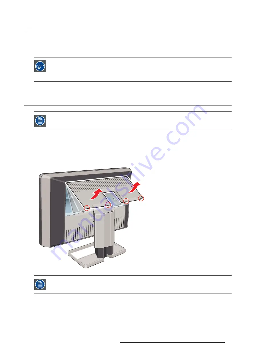
The connector compartment cover should be removed to get access to the connectors.

To remove the connector compartment cover

1. Gently lift the clips at one of the handles of the connector compartment cover to release that side of the

cover.

2. Do the same at the other side of the cover.

3. Remove the cover.

The display stand cover should be removed to get access to the cable routing channel.

To remove the display stand cover

1. Gently press and hold the clips at the inside top of the cover.

K5902055 CORONIS FUSION 6MP 14/11/2014

7

Summary of Contents for MDCC-6230

Page 1: ...Coronis Fusion 6MP User Guide MDCC 6230 K5902055 04 14 11 2014...

Page 2: ...Barco nv President Kennedypark 35 8500 Kortrijk Belgium Phone 32 56 23 32 11 Fax 32 56 26 22 62 Support www barco com esupport Visit us at the web www barco com Printed in Belgium...

Page 3: ...dvanced operation 19 5 1 OSD menu position 19 5 2 OSD menu language 19 5 3 OSD menu automatic close function 19 5 4 Power status indicator light 20 5 5 Key indicator lights 20 5 6 Power lock function...

Page 4: ...5 7 Repackaging instructions 37 7 1 Repacking your display 38 8 Important information 39 8 1 Safety information 39 8 2 Environmental information 40 8 3 Regulatory compliance information 43 8 4 EMC not...

Page 5: ...racteristics on the market setting new standards for brightness and contrast even from a wide viewing angle Use the instructions in this guide to install your Coronis Fusion 6MP display and discover a...

Page 6: ...1 Welcome 4 K5902055 CORONIS FUSION 6MP 14 11 2014...

Page 7: ...play front view Overview 1 8 3 2 4 5 6 7 Image 2 1 Front view 1 USB downstream connectors 2 Left Up key 3 Right Down key 4 Menu Enter key 5 Stand by Cancel key 6 Power status indicator light 7 Control...

Page 8: ...ut 4 DisplayPort 2 video input 5 Connector compartment cover 6 Neck cover 7 DisplayPort 1 video input 8 Display stand cover 9 DVI 1 video input 10 Ethernet connector see note below 11 USB upstream con...

Page 9: ...overs The connector compartment cover should be removed to get access to the connectors To remove the connector compartment cover 1 Gently lift the clips at one of the handles of the connector compart...

Page 10: ...the display stand is locked with a red hook to prevent damage during transportation You ll have to remove this hook before adjusting your display height position To remove the hook 1 Position the disp...

Page 11: ...ansportation insert the short red end of the hook back into the stand of your display 3 3 Adjusting the display position Now that the height positioning system of your display is unlocked you can adju...

Page 12: ...es can have the same video input connected as well but only one video input is allowed on each side of your display To connect the signal cables to the display 1 Connect one head of the display contro...

Page 13: ...ivered in the packaging 3 6 Routing the cables To route the cables 1 Route all connected cables through the cable routing channel in the stand of your display Tip The cable straps at the inside of the...

Page 14: ...the VESA 100 mm stan dard Use an arm that can support the weight of the display Refer to the technical specifica tions of this display for the applicable weight CAUTION You should mount the panel in...

Page 15: ...r sides pulled open 3 Lift the plastic frame that covers the fixation of the panel to the stand Turn it for 45 degrees to uncover the fixation screws 4 Unscrew the four fixation screws fixing the pane...

Page 16: ...ching page 16 2 Turn on the computer connected to your display If you have properly installed your display and display controller the Windows start up messages will appear once the boot procedure is f...

Page 17: ...usage A good screen saver displays moving content In case you are working with the same image or an application with static image elements for several hours continuously so that the screen saver is n...

Page 18: ...up 1 Gently sweep your finger over the bottom right hand side of your display As a result the keys will light up and are now available for further actions However if no further actions are taken with...

Page 19: ...isplay to Stand by using the control wheel 1 Press the control wheel once a small window pops up Press the control wheel again to confirm As a result the display will switch to stand by mode and the p...

Page 20: ...D menus About OSD menu navigation Navigating through the OSD menu can be done by using the keys or by using the control wheel How to navigate through the OSD menus using the keys 1 Use the Right Down...

Page 21: ...s avail able for the OSD menu of your Coronis Fusion 6MP To change the language of the OSD menu 1 Bring up the OSD main menu 2 Navigate to the Configuration User Interface Menu menu 3 Enter the Langua...

Page 22: ...lighting up the key indicator lights will dim again if no further actions are taken within the following 5 seconds However this behavior can be changed so that the key indicator lights are always on o...

Page 23: ...directly over USB with the connected PC Enabling the Ethernet over USB is only recommended when you are using a non Barco display controller If you are using a Barco display controller this communica...

Page 24: ...s properties window of your workstation Barco recommends setting DPMS activation after 20 minutes of non usage When DPMS mode is enabled on your display an additional OSD power saving function becomes...

Page 25: ...Navigate to the Configuration Calibration menu 3 Enter the Luminance Target submenu 4 Set a luminance target value as desired and confirm The default factory DICOM calibrated luminance value is avail...

Page 26: ...er the Color Temperature submenu 6 Set the Temperature value as desired and confirm 5 15 Color coordinates About color coordinates It is possible to change the color coordinates of your display Color...

Page 27: ...ay all grayscale color levels with luminance increments that are not optimal for crucial diagnostic information Studies have shown however that in medical images certain grayscale color parts contain...

Page 28: ...to select a realistic reading room when enabling ALC This can be done by following the instruc tions in Reading rooms page 26 To enable disable ALC 1 Bring up the OSD main menu 2 Navigate to the Conf...

Page 29: ...mbient light To select a reading room 1 Bring up the OSD main menu 2 Navigate to the Configuration Calibration Ambient Light menu 3 Enter the Reading Room submenu 4 Select one of the available reading...

Page 30: ...rom the moment it is installed and running MediCal QAWeb Agent will take over from Embedded QA and overwrite any settings which were applied by Embedded QA 5 21 2 DICOM status report About DICOM statu...

Page 31: ...Warning Pressing a key during the compliance check will abort the check 5 21 4 DICOM calibration About DICOM calibration The DICOM calibration will add a correction to the current DICOM curve to appro...

Page 32: ...aling is only possible when the resolution of your display s video input signal is less than or equal to half the maximum resolution of the display To enable disable image scaling 1 Bring up the OSD m...

Page 33: ...urces menu 3 Enter the Image Source Selection submenu 4 Select one of the available image source selection modes and confirm 5 24 Video input signals Your Coronis Fusion 6MP display automatically dete...

Page 34: ...encoding following the High Dynamic Range HDR standard usually used on color displays HDR2 HDR2 is a Barco specific mode featuring 10 bit video encoding following the High Dynamic Range HDR standard b...

Page 35: ...cale Conversion submenu 4 Select one of the available color conversion modes and confirm 5 27 EDID timings Your Coronis Fusion 6MP display automatically detects the connected video input sig nals and...

Page 36: ...tus About display status The Status submenu of the OSD menu provides info on the current status of your display runtimes tem peratures etc the status of the connected image sources video encoding mode...

Page 37: ...hol solvents at higher concentration 5 Strong alkalis lye strong solvents Acid Detergents with fluoride Detergents with ammonia Detergents with abrasives Steel wool Sponge with abrasives Steel blades...

Page 38: ...6 Cleaning your display 36 K5902055 CORONIS FUSION 6MP 14 11 2014...

Page 39: ...packaging 1 2 3 4 5 6 7 8 Image 7 1 Repack instructions 1 Box 5 Coronis Fusion 6MP display 2 System CD Documentation CD and User guide 6 Top buffer 3 Bottom buffer 7 Display controller box 4 Power sup...

Page 40: ...power supply in the dedicated cavity of the bottom buffer 5 Put the Coronis Fusion 6MP display in its original bag and place it in the box with its panel facing downwards 6 Put the top buffer on top o...

Page 41: ...n patient care equipment Equipment primarily for use in a health care facility that is intended for use where contact with a patient is unlikely no applied part The equipment may not be used with life...

Page 42: ...ce in a cupboard or another closed location heed the necessary space between the set and the sides of the cupboard Installation Place the device on a flat solid and stable surface that can support the...

Page 43: ...oHS Chinese Mainland RoHS RoHS Barco RoHS MCV According to the China Administration on Control of Pollution Caused by Electronic Information Products Also called RoHS of Chinese Mainland the table bel...

Page 44: ...mation Products EIP that are sold within Chinese Mainland must comply with the Electronic Information Products Pollution Control Labeling Standard of Chinese Mainland marked with the Environmental Fri...

Page 45: ...ed in accordance with the instructions may cause harmful interference to radio communications However there is no guarantee that interference will not occur in a particular installation If this device...

Page 46: ...uipment the user is encouraged to try to correct the interference by one or more of the following mea sures Reorient or relocate the receiving antenna or equipment Increase the separation between the...

Page 47: ...y magnetic fields should be at levels characteristic of a typical location in a typical commercial or hospital environment Conducted RF IEC 61000 4 6 Radiated RF IEC 61000 4 3 3 Vrms 150 kHz to 80 MHz...

Page 48: ...0 01 0 12 0 12 0 23 0 1 0 38 0 38 0 73 1 1 2 1 2 2 3 10 3 8 3 8 7 3 100 12 12 23 At 80 MHz and 800 MHz the separation distance for the higher frequency range applies 3 Field strengths from fixed tran...

Page 49: ...rt 15 of the FCC rules Class A or Class B Indicates the device is approved according to the UL regulations Indicates the device is approved according to the UL regulations for Canada and US Indicates...

Page 50: ...ates Alternating Current AC Stand by Equipotentiality 8 6 Legal disclaimer Disclaimer notice Although every attempt has been made to achieve technical accuracy in this document we assume no responsibi...

Page 51: ...Patent information This product is covered under the following intellectual property rights US Patent RE43 707 US Patent 7 038 186 US Patent 7 166 829 US Patent 6 950 098 European Patent 1 274 066 Eur...

Page 52: ...41 mm Dimensions packaged W x H x D 869 x 764 x 400 mm Net weight with stand 26 5 kg Net weight w o stand 20 kg Net weight packaged with stand 36 5 kg Net weight packaged w o stand N A Height adjustme...

Page 53: ...MITED TO THE IMPLIED WARRANTIES OF MERCHANTABILITY AND FITNESS FOR A PARTICU LAR PURPOSE IN NO EVENT SHALL THE COPYRIGHTHOLDER OR ANY OTHER CONTRIBUTOR BE LIABLE FOR DIRECT INCIDENTAL OR CONSEQUENTIAL...

Reviews: