3. Connections
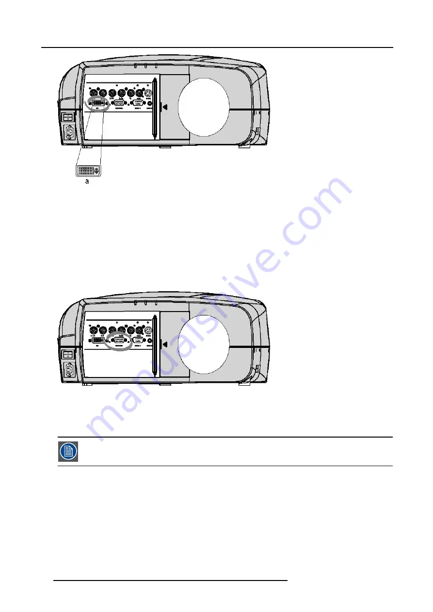
Image 3-7
a
DVI-I type connector, analog link (4 pins at the right side of the connector) not supported
How to select the DVI Input ?
1. Press
5
on the RCU
Note:
Another way for selecting this input is via the Menu.
3.2.7
Computer input
Input specification
TTL sync input : U
min
= 2.0 V
RGB input = 0.7 V
pp
± 3dB
Image 3-8
What can be connected ?
•
RGBHV
•
RG
S
B
Composite sync only possible on Green
How to select a computer input ?
1. Press
2
on the RCU
Note:
Another way for selecting this input is via the Menu.
3.2.8
Communications Connections
Overview
•
24
R5976491 IQ PRO G500 01/02/2007
Summary of Contents for iQ PRO G500
Page 1: ...iQ PRO G500 Owner s Manual R9003081 R5976491 09 01 02 2007...
Page 6: ......
Page 10: ...Table of contents 4 R5976491 IQ PRO G500 01 02 2007...
Page 17: ...2 Installation Guidelines 1 2 3 4 Image 2 1 R5976491 IQ PRO G500 01 02 2007 11...
Page 24: ...2 Installation Guidelines 18 R5976491 IQ PRO G500 01 02 2007...
Page 34: ...3 Connections 28 R5976491 IQ PRO G500 01 02 2007...
Page 48: ...4 Getting started 42 R5976491 IQ PRO G500 01 02 2007...
Page 54: ...5 Source Selection Image 5 9 48 R5976491 IQ PRO G500 01 02 2007...
Page 60: ...6 General Menu Image 6 10 54 R5976491 IQ PRO G500 01 02 2007...
Page 80: ...7 Image Menu Image 7 38 74 R5976491 IQ PRO G500 01 02 2007...
Page 90: ...8 Tools Menu 84 R5976491 IQ PRO G500 01 02 2007...
Page 100: ...10 Lamp Menu 94 R5976491 IQ PRO G500 01 02 2007...
Page 110: ...11 Image files menu Image 11 20 104 R5976491 IQ PRO G500 01 02 2007...
Page 180: ...C Troubleshooting 174 R5976491 IQ PRO G500 01 02 2007...
Page 188: ...E Standard Image Files 182 R5976491 IQ PRO G500 01 02 2007...


