background image

7. Advanced

When the menu has been exited for more than 1 minute, the advanced user password has to be re entered.

7.2

Using the Dialog boxes

How to use the dialog boxes ?

Some parameters are modified by means of a dialog box, where selections can be made and/or values can be entered.

The values can be entered in several ways:

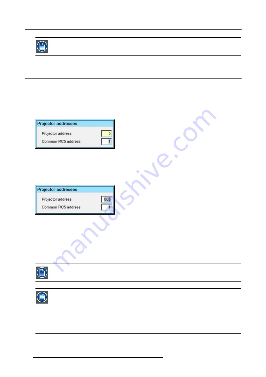
Entering numeric values using the numeric keys on the remote control

1. Press

ENTER

to activate the input field.

Image 7-1

2. Key in the desired value.

Entering numeric values using the arrow keys on the remote control

1. Press

ENTER

to activate the input field.

2. Press

or

to select the digit to be changed.

Image 7-2

3. Press

or

to increase or decrease the value.

Entering numeric values using the arrow keys on the local keypad

1. Press

ENTER

to activate the input field.

2. Press

or

to select the digit to be changed.

3. Press

or

to increase or decrease the value.

To confirm the changes always press ENTER.

Use

or

to browse between the different fields.

In some cases an alphanumeric value (file name, ...) has to be entered. Use

or

to scroll through the char-

acter values once the input field is activated.

Following characters can be browsed in this particular order:

Decimal scroll list: 0123456789

Signed decimal scroll list: 0123456789-

ASCII scrolllist:ABCDEFGHIJKLMNOPQRSTUVWXYZ012-*/&@#.;.abcdefghijklmnopqrstuvwxyz

42

R59770079 BARCO ID H250/500 23/07/2007

Summary of Contents for iD H250

Page 1: ...Barco iD H250 500 Owners manual R9010520 R9010570 R59770079 01 23 07 2007...

Page 2: ...duct revision Firmware V1 20 Barco nv Presentations Noordlaan 5 8520 Kuurne Phone 32 56 36 82 11 Fax 32 56 35 86 51 E mail presentations bid barco com Visit us at the web www barco com Printed in Belg...

Page 3: ...t by itself cause the resulting work to be covered by the GNU General Public License However the source code for this file must still be made available in accordance with section 3 of the GNU General...

Page 4: ...uted to programs or special electronic circuitry provided by the purchaser e g interfaces Normal wear as well as normal maintenance are not subject to the guarantee provided by Barco either The enviro...

Page 5: ...5 5 1 RCU Local keypad 25 5 2 Terminology overview 27 5 3 Switching on 28 5 4 Setting up the RCU address 29 5 5 Setting up the projector address only if necessary 30 5 6 Setting up the orientation 31...

Page 6: ...age files 68 7 7 2 Load file 69 7 7 3 Forced file load 70 7 7 4 Auto Image 71 7 7 5 Edit file 72 7 7 6 Save as create a custom file 74 7 7 7 Rename file 74 7 7 8 Copy 75 7 7 9 Delete 76 7 8 Display se...

Page 7: ...ed in a carton box To provide protection during transportation the projector is surrounded with foam The package is secured with banding and fastening clips R824562 R824561 R824518 cable basket R72440...

Page 8: ...move the 8 foam parts 6 Loosen and remove the 3 screws spacers fixing the projector to the wooden board 7 Remove the projector from the board Save the original shipping carton and packing material the...

Page 9: ...Precaution Environment condition check A projector must always be mounted in a manner which ensures the free flow of clean air into the projectors ventilation inlets as well as free flow at the ventil...

Page 10: ...becomes more important As a general rule darken the room to the point where there is just sufficient light to read or write comfortably Spot lighting is desirable for illuminating small areas so that...

Page 11: ...ens Formulas Projector configuration Positioning the projector Dimensions Dimensions are given in mm and inch 1inch 25 4 mm Length with different lenses see table Cold air IN Cold air IN 69 20 Cold ai...

Page 12: ...ace the batteries in the RCU To replace the batteries 1 Remove the battery cover on the backside by pushing the handle a little towards the bottom of the RCU 2 Lift up the top side of the cover at the...

Page 13: ...the lens 1 Unlock the lens by pulling the handle located on the right side of the projector Image 3 4 Image 3 5 location of the lens handle 2 Remove the lens out of its housing CAUTION Never transpor...

Page 14: ...2 X SW 0 06 PDmin 1 02 X SW 1 97 PDmax 1 2 X SW 2 36 CLD 1 2 1 6 1 PDmin 1 1 X SW 0 02 PDmax 1 51 X SW 0 02 PDmin 1 1 X SW 0 79 PDmax 1 51 X SW 0 79 CLD 1 6 2 4 1 PDmin 1 46 X SW 0 00 PDmax 2 21 X SW...

Page 15: ...n where the projector is positioned so as to have the centre of the lens coinciding with the centre of the screen Positioning the projector The position of the projector with reference to the screen m...

Page 16: ...3 Installation P PD x F a b c S S B SH SW SH SW F CD SH 2 B A A front plate Image 3 7 12 R59770079 BARCO ID H250 500 23 07 2007...

Page 17: ...s in an Off Axis installation Shifting the lens will not guarantee optimal image quality CAUTION Only for projectors containing a Server Single Board Computer The harddisk in the server is formatted i...

Page 18: ...3 Installation CAUTION Never place the projector on either side Floor Floor Image 3 9 14 R59770079 BARCO ID H250 500 23 07 2007...

Page 19: ...deo signal Connecting an S Video signal Connecting an RGB signal Connecting a Component Video signal Connecting a DVI signal Connecting a computer signal The DVI output 4 2 1 The input section Input l...

Page 20: ...a possibility to connect a VGA signal on the RGBHV input using an adapter Image 4 2 L1 LAYER 1 L1 LAYER 2 L1 LAYER 3 L1 LAYER 4 Image 4 3 Input section L1 LAYER 1 L1 LAYER 2 L1 LAYER 3 L1 LAYER 4 Ima...

Page 21: ...composite video signal 1 Connect the BNC connector to the projector s BNC video input DVD Player Image 4 5 4 2 3 Connecting an S Video signal S Video connection An S Video signal is available on the...

Page 22: ...C Connector R G B H V RGBHV R G B H V RGsB R Gs B RGBS R G B S Table 4 1 How to use the BNC s in case of different RGB signals The RGB 5 BNC input can also be used to connect a component video source...

Page 23: ...loped by DDWG Digital Display Work Group This connection standard offers two different connectors one with 24 pins that handles digital video signals only and one with 29 pins that handles both digita...

Page 24: ...onnector to the projector s Computer input Image 4 10 4 2 8 The DVI output What can be done The DVI output is a copy of the displayed image without the OSD menu and can be connected to an external mon...

Page 25: ...ns Image 4 11 The DVI output is at 1920x1080 projector s native resolution Image 4 12 4 3 Communication connections Overview RS232 RS422 Connections Ethernet Connections R59770079 BARCO ID H250 500 23...

Page 26: ...nnect the RS232 RS422 ports 1 Connect the D9 connector from the RS232 RS422 cable to the RS Input on the projector PC Serial Port Image 4 13 RS232 connection 2 When applicable connect the RS232 RS422...

Page 27: ...onnection 2 Connect the other end of the TCP IP cable into the 10 100Base T port on the projector The orange led will light up when network activity is detected See the Setup section for the network s...

Page 28: ...4 Connections 24 R59770079 BARCO ID H250 500 23 07 2007...

Page 29: ...the lens Setup the baudrate for serial communication Network settings Preferences 5 1 RCU Local keypad How controlling the projector The projector can be controlled by the local keypad or by the remot...

Page 30: ...of the remote control are switching between stand by and operational mode switching to pause blanked picture full power for immediate restarting direct access to all connected sources Diagnose LED s G...

Page 31: ...p projection for a short time press PAUSE The image disappears but full power is retained for immediate restarting 6 STBY standby button to start projector when the power switch is switched on and to...

Page 32: ...wards to previous menu 19 EFFECTS not yet implemented 20 PIP ADJUST allows to select a PiP window and change its configuration on screen 21 RC operating indication lights up when a button on the remot...

Page 33: ...g up the projector s orientation Displaying the Projector Address in Standby mode 1 Press the Address key recessed key on the RCU with a pencil 9 0 EN T ER M EN U B A C K D I G I Z O O M PH A SE PA U...

Page 34: ...rojector address set to 0 In some cases the projector address must be changed for example if an unique RCU is used to control 2 or more projectors inde pendently In the OSD menu Projector Address the...

Page 35: ...e Tool bar 2 Press to select the Installation item 3 Press to Pull down the Installation menu 4 Use or to select Orientation 5 Press to pull down the menu 6 Use or to select the desired orientation Im...

Page 36: ...d 1 Press LENS ZOOM or LENS FOCUS or LENS SHIFT on the RCU 3 1 4 2 L EN S Z O O M L EN S SH I F T L EN S F O C U S VO L C O N T R B R I G H T N Image 5 8 2 Use the arrow keys to adjust 9 0 EN T ER M E...

Page 37: ...rt of the projector allows you to communicate with any other equipment disposing of an RS232 port generally a PC used to upgrade the projector s firmware using the RS232 protocol The baudrate must be...

Page 38: ...ue DHCP DHCP setting Yes The projector will dynamically obtain its IP address from the DHCP server No The IP address needs to be entered manually Note that when selecting Fxed IP the IP settings field...

Page 39: ...ges A dialog box is shown The different executed operations are shown with a checkbox The last operation Restarting network takes a few seconds more Image 5 16 5 10 Preferences Overview Language setti...

Page 40: ...unction can be disabled if undesired or inadequate for safety reasons etc CAUTION If the Automatic startup function is enabled one must be aware of the fact that it involves safety precautions Make su...

Page 41: ...5 Setup Image 5 18 7 Press ENTER R59770079 BARCO ID H250 500 23 07 2007 37...

Page 42: ...5 Setup 38 R59770079 BARCO ID H250 500 23 07 2007...

Page 43: ...A C K D I G I Z O O M PH A SE PA U SE PI P L O G O Image 6 1 The last selected source is displayed 6 2 Selecting a source How to select a source 1 Press the digit corresponding to the desired source...

Page 44: ...6 Getting started 40 R59770079 BARCO ID H250 500 23 07 2007...

Page 45: ...d parameters are not visible they are replaced by More Menu items which are not applicable are greyed out Menu Layout A grey line gives the transition between standard and advanced parameters The exis...

Page 46: ...Press or to select the digit to be changed Image 7 2 3 Press or to increase or decrease the value Entering numeric values using the arrow keys on the local keypad 1 Press ENTER to activate the input f...

Page 47: ...brings of course some lost of quality The resolution of the projector is 1920x1080 with an aspect ratio of 16 9 Selecting a source via the local keypad the Source button on the local keypad allows to...

Page 48: ...nal How to select the S Video input 1 Press MENU to activate the Tool bar 2 Press to Pull down the Source Selection menu 3 Use or to select L2 S Video Image 7 4 4 Press ENTER to confirm your choice A...

Page 49: ...o the D15 input connector of the projector An RGB data signal can have its sync signal added in different ways refer to the Installation section for more information on the RGB sync signals accepted b...

Page 50: ...VI input on layer 3 1 Press MENU to activate the Tool bar 2 Press to Pull down the Source Selection menu 3 Use or to select L3 DVI Image 7 8 4 Press ENTER to confirm your choice A bullet indicates the...

Page 51: ...FREEZE button on the remote How to freeze the image 1 Press MENU to activate the Tool bar 2 Press to select General 3 Press to Pull down the General menu 4 Use or to select Freeze Image 7 10 5 Press E...

Page 52: ...put balance Automatic gain control AGC Manual gain control What can be done Correct image settings are important for a good image reproduction The image settings are made through a dialog box with a s...

Page 53: ...box Image 7 14 8 Use or the numeric keys on the remote or the keypad to change the contrast 7 5 1 2 Setting the Brightness Brightness adjustment Adjusting the brightness will affect the dark areas of...

Page 54: ...Tint adjustment is only applicable for NTSC video signals The tint adjustment allows the reddish and greenish tones to be corrected How to change the Tint 1 Press MENU to activate the Tool bar 2 Press...

Page 55: ...f a maximum of gradations brightness levels in the projected image How to adjust the Gamma 1 Press MENU to activate the Tool bar 2 Press to select the Image item 3 Press to Pull down the Image menu 4...

Page 56: ...e screen appears now a slider box Image 7 21 8 Use or the numeric keys on the remote or the keypad to change the Phase 7 5 1 8 Noise Reduction only for video signals How to remove noise in the image 1...

Page 57: ...namorphic 16 9 or anamorphic 2 35 1 to take advantage of the higher vertical resolution offered by the 4 3 ratio The anamorphic term means that the original wide screen image is squeezed in order to f...

Page 58: ...sources where the 16 9 setting allows the best reproduction The Auto function calculates an aspect ratio based on the information stored in the image files Selecting Auto in case of a Video source may...

Page 59: ...ntation setting is enabled How to set a custom Aspect ratio 1 Press MENU to activate the Tool bar 2 Press to select Image 3 Press to Pull down the Image menu Image 7 27 4 Use or to select Aspect ratio...

Page 60: ...or temperature 1 Press MENU to activate the Tool bar 2 Press to select the Image item 3 Press to Pull down the Image menu 4 Use or to select Color temperature 5 Press to pull down the menu 6 Use or to...

Page 61: ...31 Image 7 32 7 5 4 Film mode detection video only What can be done Some sources like common DVD material are derived from cinema 24 Hz sources 2 2 or 3 2 pull down method 0 42 83 125 167 40 80 120 16...

Page 62: ...elect the Image item 3 Press to Pull down the Image menu 4 Use or to select Film mode detection 5 Press to pull down the menu 6 Use or to enable or disable the Film mode detection Image 7 35 7 Press E...

Page 63: ...n it be done To balance the three color signals of a particular source there are conditions in fact we must know the black and the white level of the source i e 1 the source in question must be able t...

Page 64: ...Image item 4 Press to Pull down the Image menu 5 Use or to select Input balance 6 Press to pull down the menu 7 Use or to select White balance Image 7 40 8 Adjust the red white level gain on a minima...

Page 65: ...s the factory input balance setting The input balance settings are stored in the image file each source has its own input balance 7 5 6 Automatic gain control AGC AGC is only for Video signals Enablin...

Page 66: ...Press to select the Image item 3 Press to Pull down the Image menu 4 Use or to select Manual Gain Control Image 7 43 5 Press ENTER A scroll bar is displayed Image 7 44 6 Use or the numeric keys on the...

Page 67: ...mes of lamp 1 and lamp 2 reaches 100 hours switching from one lamp to another happens only at switching on of the projector and not during operation When the lamp fails or reaches its maximum runtime...

Page 68: ...ining lamp Again the lamp error is logged and shown on the screen How to select the lamp mode 1 Press MENU to activate the Tool bar 2 Press to select the Lamp item 3 Press to Pull down the Lamp menu 4...

Page 69: ...ng showing that hot restrike restart of the lamp is impossible during that time laps 60 sec 7 6 3 History How to view the history 1 Press MENU to activate the Tool bar 2 Press to select the Lamp item...

Page 70: ...he serial number of the new lamp serial number 0000000 will not be accepted 7 6 5 Clear lamp error Lamp error When a failure of one of the lamps has occurred a lamp logo is displayed in the left corne...

Page 71: ...to confirm the lamp error removal Confirm The lamp error logo is removed from the screen 7 6 6 Lamp runtime warning What can be done When the lamp has reached a predetermined runtime a warning message...

Page 72: ...s standard files When a new source corresponds to one of these files a custom file is created The file is not automatically saved as a custom file The Save as function allows to create and save a cust...

Page 73: ...y AutoImage How to load a file 1 Press MENU to activate the Tool bar 2 Press to select the Image files item 3 Press to Pull down the Image files menu 4 Use or to select Load Image 7 58 5 Press ENTER A...

Page 74: ...file to be loaded 1 Press MENU to activate the Tool bar 2 Press to select the Image files item 3 Press to Pull down the Image files menu 4 Use or to select Forced file load 5 Press to open the menu 6...

Page 75: ...0 seconds depending on file Full scan tracking is done over the full range The operation takes about 1 5 minutes depending on file How to launch Auto Image 1 Press MENU to activate the Tool bar 2 Pres...

Page 76: ...file can be edited How to edit a file 1 Press MENU to activate the Tool bar 2 Press to select the Image files item 3 Press to Pull down the Image files menu 4 Use or to select Edit Image 7 62 5 Press...

Page 77: ...oose a short or long hold interval A long AGC hold interval eliminates Macrovision disturbances since the AGC is hold during a long interval thus reducing the probability to encounter a Macrovision pu...

Page 78: ...be created This custom file will then be loaded auto matically and will prevent the AutoImage from being launched How to save a file 1 Press MENU to activate the Tool bar 2 Press to select the Image f...

Page 79: ...o edit and change the values confirm with ENTER Image 7 71 7 7 8 Copy Copy a file The copy function allows to copy a file standard or custom to a custom file to the custom directory How to copy a file...

Page 80: ...file name is copied in the edit field 8 Use the keys on the remote to change the name of the destination file 7 7 9 Delete How to delete a file 1 Press MENU to activate the Tool bar 2 Press to select...

Page 81: ...up Overview Dynacolor Brilliant ColorTM mode Full screen synchronous representation Text box Menu bar position Status bar position Sliderbox position Softedge 7 8 1 Dynacolor What can be done DynaColo...

Page 82: ...tor color gamut is defined by the triangle formed by the x y coordinates of Red Green and Blue Due to the tolerance on optical components the x y values of this color gamut of each projector will diff...

Page 83: ...the Common Color Gamut is described by the 6 points of intersection of the 2 separate color gamuts G1 G2 R1 R2 B1 W1 0 x y 1 2 3 4 5 6 7 1 2 3 4 5 6 7 8 B2 W2 Gc Wc Yc Rc Mc Bc Cc Image 7 80 The Comm...

Page 84: ...ameters can be adjusted within DynaColor the x y coordinates and g Light Output of the 6 Common Color Gamut perimeter points the x y coordinates and g Light Output of the White point of the Common Col...

Page 85: ...ENTER Dynacolor g Light Output Value The value g in the Dynacolor interface represents a relative light output g 1 is the maximum available light output Assume we have a projector L 1 in the Dynacolo...

Page 86: ...he Green point Blue x y Co rdinates for the Blue point Cyan x y Co rdinates for the Cyan point Yellow x y Co rdinates for the Yellow point Magenta x y Co rdinates for the Magenta point White x y Co rd...

Page 87: ...7 Advanced Image 7 83 3 Assume the second projector has the following measured values R59770079 BARCO ID H250 500 23 07 2007 83...

Page 88: ...7 Advanced Image 7 84 84 R59770079 BARCO ID H250 500 23 07 2007...

Page 89: ...ojectors 6 In the desired values adjust the red coordinate to a common value for both projectors Tip The color bar of the adjusted coordinate will no longer be displayed in case the coordinate is not...

Page 90: ...n a laptop or PC contact Barco for more information 7 8 2 Brilliant ColorTM mode What can be done Brilliant ColorTM Texas InstrumentsTM technology allows to use secondary colors in the process of the...

Page 91: ...t signal on the monitor How to enable disable the full screen synchronous representation 1 Press MENU to activate the Tool bar 2 Press to select the Display setup item 3 Press to Pull down the Display...

Page 92: ...Tool bar 2 Press to select the Display setup item 3 Press to Pull down the Display setup menu 4 Use or to select Menu bar position menu 5 Press ENTER Image 7 92 6 Use or to position the Menu bar 7 8...

Page 93: ...this menu How to reposition the slider box 1 Press MENU to activate the Tool bar 2 Press to select the Display setup item 3 Press to Pull down the Display setup menu 4 Use or to select Slider box posi...

Page 94: ...alf of the full native size i e 960 for the left and right side and 540 for the top and bottom Softedge Width setting 1 Press MENU to activate the Tool bar 2 Press to select the Display setup item 3 P...

Page 95: ...r each color Red green Blue separately or for the 3 colors together How to adjust the black level 1 Press MENU to activate the Tool bar 2 Press to select the Display setup item 3 Press to Pull down th...

Page 96: ...7 Advanced 92 R59770079 BARCO ID H250 500 23 07 2007...

Page 97: ...ith a CLEAN TorayseeTM cloth 2 Always wipe lenses in a single direction Warning Do not wipe back and forwards across the lens surface as this tends to grind dirt into the coating 3 Do not leave cleani...

Page 98: ...8 Maintenance 94 R59770079 BARCO ID H250 500 23 07 2007...

Page 99: ...07 864 EXGA1 70 1152x864 70 63 800 94 424 1480 1152 912 864 EXGA2 70 1152x864 70 66 098 99 941 1512 1152 945 864 EXGA2 75 1152x864 75 75 199 110 092 1464 1152 1002 864 FMR 640x400i 42 323 36 440 28 57...

Page 100: ...145 820 1568 1152 930 864 NTSC 675x240 60 15 748 13 512 858 675 263 240 NTSC_LIMO_x2 834x482 60 31 496 32 252 1024 834 525 482 PAL 675x286 50 15 625 13 500 864 675 313 286 PAL_LIMO_x2 834x574 50 31 25...

Page 101: ...31 600 SXGA_ 72_1 1280x1024 72 76 699 128 854 1680 1280 1061 1024 SXGA_ 72_2 1280x1024 72 76 970 130 080 1690 1280 1069 1024 SXGA_ 75 1280x1024 75 79 974 134 997 1688 1280 1066 1024 SXGA_ 76 1280x1024...

Page 102: ...278i 25 000 15 625 31 984 1310 1024 313 278 WSXGA 60 1600x1024 60 64 137 2144 1600 1060 1024 WSXGA 60 1680x1050 60 79 178 2272 1680 1304 1050 WUXGA 60 1920x1200 60 75 194 2592 1920 1245 1200 WUXGA_2 6...

Page 103: ...to display the I2C diagnostics menu 1 Press MENU to activate the Tool bar 2 Press to select the Tools item 3 Press to Pull down the Tools menu 4 Use or to select Diagnostics 5 Press to pull down the...

Page 104: ...tal air pressure note that in case of extreme air pressures this can be set via RS232 the default factory value set being 1014 mbar For Barco certified service technicians only For more information on...

Page 105: ...ol 62 manual 62 gamma 51 General 46 getting started 39 adjust 39 source selection 39 Getting started 39 I Identification 47 image 49 52 56 Color temperature 56 noise reduction 52 settings 49 Image 48...

Page 106: ...25 27 Terminology 27 Overview 27 Removing 9 lens 9 representation 87 synchronous 87 RS232 22 Connections 22 RS422 22 Connections 22 S S Video 44 Selecting a source 39 serial comms 33 baudrate 33 setu...

Reviews: