5. Connections
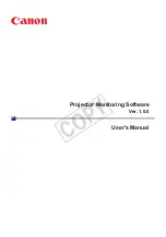
Image 5-13
Left side : DVI connection on Layer 2, right side : DVI connection on Layer 0
Note that the 2 DVI outputs are identical and are processed in the same way in the projector
5.3.7
Connecting a computer signal
How to connect a computer signal
1. Connect the D15 connector to the projector’s Computer input
Image 5-14
5.3.8
The DVI output
What can be done ?
The DVI output is a copy of the projector’s complete desktop image (containing also the source windows) and can be connected
to an external monitor. Some monitors can fail to synchronize on the DVI signal, in this case disable the
Full screen synchronous
representation
function in the
Display Settings
menu.
26
R5976992 ICON H250/400 13/12/2006
Summary of Contents for iCon H250
Page 1: ...iCon H250 400 Owners manual Preliminary R9010510 R9010500 R5976992 0A 13 12 2006...
Page 10: ...Table of contents 4 R5976992 ICON H250 400 13 12 2006...
Page 34: ...5 Connections 28 R5976992 ICON H250 400 13 12 2006...
Page 60: ...6 Setup 54 R5976992 ICON H250 400 13 12 2006...
Page 103: ...7 Advanced Image 7 84 R5976992 ICON H250 400 13 12 2006 97...
Page 130: ...8 Network centric operations 124 R5976992 ICON H250 400 13 12 2006...
Page 144: ...11 SNMP services 138 R5976992 ICON H250 400 13 12 2006...
Page 146: ...12 Maintenance 140 R5976992 ICON H250 400 13 12 2006...
Page 152: ...13 Image files 146 R5976992 ICON H250 400 13 12 2006...