background image

2. Installation

DVI

DVI

DVI

DVI

1

2

DESKTOP INPUT

DESKTOP INPUT

IN1

IN1

IN2

IN2

L1

L1

STEREO INPUT

STEREO INPUT

STEREO OUTPUT

STEREO OUTPUT

L2

L2

L3

L3

IN1

IN1

IN2

IN2

IN1

IN1

IN2

IN2

RS 232 C

RS 232 C

DVI

DVI

R.C.

R.C.

IR Emitter

Active Glasses

IR Emitter

Image Generator

Image Generator

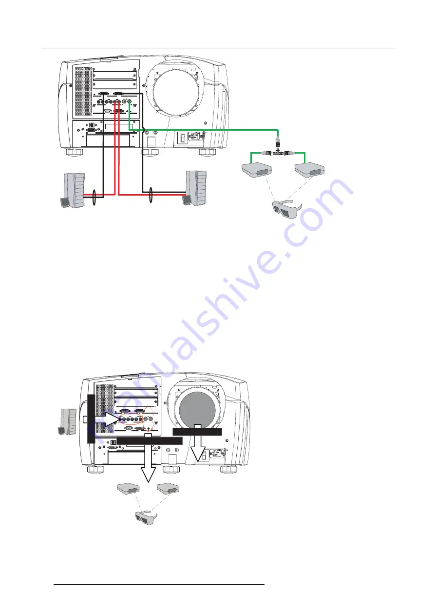
Image 2-27
Connecting stereo sources

2. Connect the BNC connector to the stereo IR emitter

Stereo settings

Different stereo settings have to be done :

stereo

input

settings in the Image menu : to match the Image generator to the projector. "Input stereo sync", page 64

stereo

output & system

settings in the Display setup menu : to match the projector to the emitters ,..."Stereo System Setup",

page 138

stereo

display

settings in the Display setup menu : to decide how to display the video content. "Stereo display settings", page

118

DVI 22

DESKTOP INPUT

DESKTOP INPUT

IN2

IN2

L1

L1

STEREO INPUT

STEREO INPUT

STEREO OUTPUT

STEREO OUTPUT

L2

L2

L3

L3

IN1

IN1

IN2

IN2

IN1

IN1

RS 232 C

RS 232 C

DVI

DVI

IR Emitter

Active Glasses

IR Emitter

Image Generator

Stereo output & system settings

Stereo input settings

Stereo display settings

Image 2-28
Stereo settings

26

R59770718 GALAXY NW SERIES 20/06/2013

Summary of Contents for Galaxy NW R9040406

Page 1: ...Galaxy NW series User guide R9040411 R9240411 R9040406 R9240406 R59770718 01 20 06 2013...

Page 2: ...Barco nv Advanced Visualization Systems Noordlaan 5 B 8520 Kuurne Phone 32 56 36 82 11 Fax 32 56 36 84 86 Support www barco com esupport Visit us at the web www barco com Printed in Belgium...

Page 3: ...ems from other types of waste and recycle them responsibly to promote the sustainable reuse of material resources For more information about recycling of this product please contact your local city of...

Page 4: ...red during transport as well as for material and manufacturing faults Barco must be informed immediately in writing of any complaints The period of guarantee begins on the date of transfer of risks in...

Page 5: ...o o o o o Remote control exclude PCB x o o o o o O Indicates that this toxic or hazardous substance contained in all of the homogeneous materials for this part is below the limit requirement in SJ T1...

Page 6: ...Turkey RoHS compliance T rkiye Cumhuriyeti EEE Y netmeli ine Uygundur Republic of Turkey In conformity with the EEE Regulation...

Page 7: ...he projector 35 3 2 Starting up the projector 36 3 3 Setting up the Remote Control Unit address 38 3 4 Setting up the projector address only if necessary 39 3 5 Setting up the orientation 40 3 6 Adjus...

Page 8: ...de 112 5 7 4 2 CLO Target 113 5 7 4 3 Linked CLO 114 5 8 General 114 5 8 1 Identification 114 5 8 2 Pause 115 5 8 3 Freeze 115 5 8 4 Standby Timer 116 5 8 5 Desktop 117 5 9 Display setup 117 5 9 1 Tex...

Page 9: ...72 5 11 4 Operation options 173 5 11 4 1 AutoImage 173 5 11 4 2 Warning messages 173 6 Maintenance 175 6 1 Maintenance timing 175 6 2 Visual checks 176 6 3 Cleaning housing and mechanical structure 17...

Page 10: ...Table of contents 4 R59770718 GALAXY NW SERIES 20 06 2013...

Page 11: ...bject Font overview Buttons are indicated in bold e g OK Menu items are indicated in italic Step related notes tips warnings or cautions are printed in italic Procedure related notes tips warnings or...

Page 12: ...l Unit RCU 2 batteries 1 Power cord with outlet plug type CEE 1 Power cord with outlet plug type NEMA L6 20P 1 Galaxy NW series User guide 1 DLP Projector Safety manual 1 Packaging The projector is pa...

Page 13: ...was inspected and found to be free of mechanical and electrical defects As soon as the projector is unpacked inspect for any damage that may have occurred in transit If damage is found file claim with...

Page 14: ...1 General 8 R59770718 GALAXY NW SERIES 20 06 2013...

Page 15: ...projector is subject to airborne contaminants such as that produced by smoke machines or similar these deposit a thin layer of greasy residue upon the projectors internal optics and imaging electronic...

Page 16: ...ms of gain The gain of screens range from a white matte screen with a gain of 1 x1 to a brushed aluminized screen with a gain of 10 x10 or more The choice between higher and lower gain screens is larg...

Page 17: ...sions Dimensions below are given in mm and inch 1 inch 25 4 mm Air flow guidelines The hot air outlet at the rear side of the projector can reach high temperatures due to the high power lamp Do not co...

Page 18: ...advised to also use an open projector support frame rather than a full support plate Image 2 3 Cool air intake Image 2 4 Cool air intake directions and restrictions Projector tilt range The tilt range...

Page 19: ...mm 500 mm Image 2 7 Dimensions free space around the projector 2 3 Battery Installation in the RCU How are the batteries delivered The batteries not yet installed to save the battery life time are de...

Page 20: ...aintenance appendix for more information about lens cleaning 2 4 2 Lens formulas Formulas Metric Formulas meter Inch formulas inch TLD 0 73 1 PD 0 71 x SW 0 09 PD 0 71 x SW 3 55 TLD 1 2 1 PD 1 14 x SW...

Page 21: ...dark on the screen The table below gives an overview of the shift capabilities in function of the lens Lens shift range Vertical shift Horizontal shift TLD 0 73 1 up down 22 left right 9 TLD 1 2 1 TL...

Page 22: ...lens holder 4x M5x12 screws delivered with the projector and with the lens Installing the lens 1 Remove the lens interface plate from the lens holder if it is still mounted to it 2 Fix the lens inter...

Page 23: ...age 2 14 Lens installation 2 5 Projector configuration CAUTION Projectors in ceiling configuration must have their second pump being connected mechanically and electrically If no second pump is presen...

Page 24: ...ens coinciding with the centre of the screen Positioning the projector The position of the projector with reference to the screen may also be different depending on the installation Basically the proj...

Page 25: ...S B S H S W S H S W F C D S H 2 B A A ref Front plate Image 2 16 ON Axis projector installation a Side view b Top view c Back view x Optical axis projection lens p Projector s Screen F Floor R5977071...

Page 26: ...17 OFF Axis projector installation a Side view b Top view c Back view x Optical axis projection lens p Projector s Screen F Floor A 100 Off Axis position means that the position of the centre of the...

Page 27: ...hase 12 Amps 50 60 Hz NW 12 220 240V single phase 12 Amps 50 60 Hz Galaxy NW 12 220 240V single phase 12 Amps 50 60 Hz Galaxy NW 7 220 240V single phase 12 Amps 50 60 Hz Power connection 1 Use the sup...

Page 28: ...nel The signal input output section The input output section has a modular architecture i e it is composed of several 5 slots which can be equipped with different input modules The different available...

Page 29: ...olds Ethernet RJ45 connection DVI desktop input LCD display 2 7 3 Connecting a DVI signal Connecting a DVI signal 1 Connect the DVI cable to one of the projector s DVI inputs DVI DVI DVI DVI 1 2 DESKT...

Page 30: ...e 2 7 5 DVI output DVI output DVI DVI DVI DVI 1 2 DESKTOP INPUT DESKTOP INPUT IN1 IN1 IN2 IN2 L1 L1 STEREO INPUT STEREO INPUT STEREO OUTPUT STEREO OUTPUT L2 L2 L3 L3 IN1 IN1 IN2 IN2 IN1 IN1 IN2 IN2 RS...

Page 31: ...STEREO OUTPUT STEREO OUTPUT L2 L2 L3 L3 IN1 IN1 IN2 IN2 IN1 IN1 IN2 IN2 RS 232 C RS 232 C DVI DVI R C R C Image 2 25 Stereo sync inputs The BNC connectors are the stereo output sync signals These sig...

Page 32: ...tch the Image generator to the projector Input stereo sync page 64 stereo output system settings in the Display setup menu to match the projector to the emitters Stereo System Setup page 138 stereo di...

Page 33: ...l dedicated network Following operations are made possible file transfer for firmware upgrade easy adjustment of projector storage of multiple projector configurations and set ups wide range of contro...

Page 34: ...MAC Address of the projector This is a non adjustable value programmed into the Ethernet board IP Address Current IP Address of the projector This is a non adjustable value Subnet Mask Subnet Mask Thi...

Page 35: ...Image 2 31 5 Push the cursor key or to highlight the desired parameter 6 Use the cursor key or the numeric keys on the RCU or the local keypad to edit and change the values 7 Press Apply settings to a...

Page 36: ...onnector from the RS232 cable to the RS232 input on the projector DVI DVI DVI DVI 1 2 DESKTOP INPUT DESKTOP INPUT IN1 IN1 IN2 IN2 L1 L1 STEREO INPUT STEREO INPUT STEREO OUTPUT STEREO OUTPUT L2 L2 L3 L...

Page 37: ...PUT STEREO OUTPUT STEREO OUTPUT L2 L2 L3 L3 IN1 IN1 IN2 IN2 IN1 IN1 IN2 IN2 RS 232 C RS 232 C DVI DVI R C R C WAN LAN1 LAN2 LAN3 LAN4 LAN5 LAN6 Network switch Image 2 34 Linking projectors 2 7 11 2 Li...

Page 38: ...IN2 IN1 IN1 IN2 IN2 RS 232 C RS 232 C DVI DVI R C R C DVI DVI DVI DVI 1 2 DESKTOP INPUT DESKTOP INPUT IN1 IN1 IN2 IN2 L1 L1 STEREO INPUT STEREO INPUT STEREO OUTPUT STEREO OUTPUT L2 L2 L3 L3 IN1 IN1 I...

Page 39: ...SE To stop projection for a short time press PAUSE The image disappears but full power is retained for immediate restarting 6 STANDBY Standby button to start projector when the power switch is switche...

Page 40: ...ront panel allows to inform the user on the status of the projector and other information like warnings etc DESKTOP INPUT Galaxy NW 12 standby Image 2 38 LCD Display See the Appendix for a listing of...

Page 41: ...ctor 1 Switch the power switch to 1 DVI DVI DVI DVI 1 2 DESKTOP INPUT DESKTOP INPUT IN1 IN1 IN2 IN2 L1 L1 STEREO INPUT STEREO INPUT STEREO OUTPUT STEREO OUTPUT L2 L2 L3 L3 IN1 IN1 IN2 IN2 IN1 IN1 IN2...

Page 42: ...see Network settings IP address Baudrate RCU private address RCU common address Galaxy NW 12 standby Galaxy NW 12 150 158 193 179 Hostname Private 1 Common 0 57600 Image 3 4 Standby status 3 2 Starti...

Page 43: ...arted up This may take up to 15 seconds During this phase the LCD display and the keypad are lit 1 The progression is shown with the asterisk characters adding up 2 This is followed by the projector P...

Page 44: ...ode 1 Press the Address key recessed key on the RCU with a pencil 9 0 EN T ER M EN U B A C K D I G I Z O O M PH A SE P A U SE PI P L O G O Image 3 8 The projector s address will be displayed on the sc...

Page 45: ...55 0 9 is used for RCU communication 0 255 being used for RS232 serial communication Common address address may be 0 or 1 How to change the projector s address 1 Press MENU to activate the Tool bar 2...

Page 46: ...and a bullet shows the active configuration 3 6 Adjusting the lens What must be done Depending on the projection distance and the lens used the image may not be at the desired size position and or may...

Page 47: ...IGHTN Image 3 12 2 Use the arrow keys to adjust 9 0 ENTER MENU BACK DIGI ZOOM PHASE PAUSE PIP LOGO Image 3 13 How to Zoom focus or shift in the OSD 1 Press MENU to activate the Tool bar 2 Press to sel...

Page 48: ...u to communicate with any other equipment disposing of an RS232 port generally a PC using the RS232 protocol The baud rate must be set to the same value on both the projector and the other equipment H...

Page 49: ...language Image 3 18 7 Press ENTER The language is adapted and a bullet shows the active selection 3 8 2 Automatic startup What can be done The automatic startup allows to bypass the standby state i e...

Page 50: ...o activate the Tool bar 2 Press to select the Installation item 3 Press to Pull down the Installation menu 4 Use or to select Automatic startup 5 Press to pull down the menu 6 Use or to enable disable...

Page 51: ...Master i e it allows to add the projector to the different control loops by a simple check CLO adding the projector to this control loop will allow the brightness light output of the projector to be...

Page 52: ...lock must be connected prior to check ing the Stereo boxes in the Linked projectors dialog box of the Master projector How to start up the linked projector menu 1 Press MENU to activate the Tool bar 2...

Page 53: ...g box is displayed Image 3 23 How to set a projector to Master 1 In the linked projector menu of the projector to be set as Master Select the Master check box and press ENTER R59770718 GALAXY NW SERIE...

Page 54: ...by the Master For example IP address 150 158 193 110 3 Select and press ENTER for the desired parameters to be controlled by the master i e CLO and or Dynacolor and or Stereo It is advised to declare...

Page 55: ...ote control AUT AUTO IMAGE O IMAGE PC PC RGB RGB VIDEO VIDEO Fire W Fire Wire ire DVI DVI IQ PC IQ PC SDI SDI S VIDEO S VIDEO PHASE PHASE TINT TINT COLOR COLOR BRIGHTN BRIGHTN CONTR CONTR ZOOM ZOOM DI...

Page 56: ...4 Getting started 50 R59770718 GALAXY NW SERIES 20 06 2013...

Page 57: ...in this manual are of the advanced type all the items are visible The menus seen by a standard user on the screen will hence not correspond with the menus in the manual i e the advanced items will no...

Page 58: ...ic keys on the remote control 1 Press ENTER to activate the input field Image 5 2 2 Key in the desired value Entering numeric values using the arrow keys on the remote control 1 Press ENTER to activat...

Page 59: ...enu bar are adapted automatically depending on the type of boards installed in the projector For example L1 PC L1 DVI L3 DVI 1 L3 DVI 2 In this case an VGA DVI board is installed in the first layer L1...

Page 60: ...t stereo sync Passive Infitec Passive to Active Stereo 5 4 1 Image settings 5 4 1 1 Setting the Contrast Contrast adjustments Adjust the contrast to brighten the white parts of the image It is recomme...

Page 61: ...7 Press ENTER On the screen appears now a slider box Image 5 6 8 Use or the numeric keys on the remote or the keypad to change the brightness 5 4 1 3 Gamma Gamma adjustment The gamma parameter determi...

Page 62: ...the screen appears now a slider box Image 5 8 8 Use or the numeric keys on the remote or the keypad to change the Phase 5 4 2 Aspect ratio Aspect ratios The standard aspect ratio used in broadcast tel...

Page 63: ...5 1 Image 5 11 Aspect ratios in native HDTV DVD sources 16 10 Image 5 12 Aspect ratio for WUXGA 1920x1200 What can be done The aspect ratio setting forces the projector to project an image using a def...

Page 64: ...The Auto function calculates an aspect ratio based on the information stored in the image files whereas Custom allows to set a personnel ratio The aspect ratio setting only affects the active source...

Page 65: ...entation setting is enabled How to set a custom Aspect ratio 1 Press MENU to activate the Tool bar 2 Press to select Image 3 Press to Pull down the Image menu Image 5 15 4 Use or to select Aspect rati...

Page 66: ...parately How to select a preset color temperature 1 Press MENU to activate the Tool bar 2 Press to select the Image item 3 Press to Pull down the Image menu 4 Use or to select Color temperature 5 Pres...

Page 67: ...f a particular source there are conditions in fact we must know the black and the white level of the source i e 1 the considered source must be able to generate a white signal ideally a 100 white back...

Page 68: ...balance 5 Press to pull down the menu 6 Use or to select Automatic Black level 7 Press to pull down the menu 8 Use or to enable ON or to disable OFF Automatic Black level Image 5 22 9 Press ENTER to c...

Page 69: ...appear on the black part of the image 12 Adjust the Blue black level until bright spots appear on the black part of the image 13 Adjust the Red black level until bright spots appear on the black part...

Page 70: ...until bright spots appear on the white part of the image 13 Adjust the Red white level gain until bright spots appear on the white part of the image The projected image should now be noisy neutral gre...

Page 71: ...t the input while the Invert Stereo see Display setup acts on the stereo emitter output How to swap the fields 1 Press MENU to activate the Tool bar 2 Press to select the Image item 3 Press to Pull do...

Page 72: ...jector has the Passive Infitec stereo option on board the according menu item becomes enabled The moment you select a Passive Infitec stereo source you must make the selection in the OSD to move the P...

Page 73: ...the projector to avoid image artifacts both input signals must be identical resolution timing format and externally frame locked Active image features and restrictions Both input signals are displayed...

Page 74: ...t input signal is connected and confirm by pressing Enter Image 5 35 Note In case of Infitec stereo mode Source 1 must be linked to the Right image and Source 2 must be linked to the Left image This i...

Page 75: ...radio button next to Status On Image 5 37 A message can be read Please select a stereo display mode 3 Click OK to store the Status On setting and leave the dialog box 4 Browse to Display setup Stereo...

Page 76: ...e source available Barco logo 3 Browse to Installation Scaled patterns and select Moving Hatch Image 5 40 You should now see the Moving Hatch pattern and the Left image content at the same time 5 5 Im...

Page 77: ...otation of the image file happens as follows Standard SXGA 60 xml Type of file standard or custom Resolution Vertical freq file extension xml Image 5 41 5 5 2 Load file When to load a file In some cas...

Page 78: ...the user wants only one particular file to be loaded for a particular input source i e to prevent the automatic load of an inadequate file One can link a file to every input of each layer If a file is...

Page 79: ...lculates measures several source parameters Total pixels per line Start pixel Phase Contrast Brightness levels Auto Image only works for data images The measure of the total number of pixels per line...

Page 80: ...file menu makes it possible to change the settings of the file according to the real settings of the connected source Consult the source specifications before entering the data only the active file ca...

Page 81: ...riod in ns Active vertical lines Vertical start in lines Advanced settings for Analog Data sources e g RGB HS VS The advanced button enables the advanced settings for a data source Image 5 48 Color sp...

Page 82: ...M 5W changing the UsePictureBox settings also inverts the interlacing 5 5 6 Save as create a custom file Creating a custom file When the loaded file is a standard file there is a possibility of saving...

Page 83: ...splayed Use or or the numeric keys on the remote or the keypad to edit and change the values confirm with ENTER Image 5 54 5 5 8 Copy Copy a file The copy function allows to copy a file standard or cu...

Page 84: ...s copied in the edit field 8 Use the keys on the remote to change the name of the destination file 5 5 9 Delete How to delete a file 1 Press MENU to activate the Tool bar 2 Press to select the Image f...

Page 85: ...mage inside the projector a correct geometry can be achieved on curved screens without requiring additional computational power on the IG s side 5 6 2 Geometry files Description A geometry file contai...

Page 86: ...etry menu How to access the Geometry menu 1 Press MENU to activate the Tool bar 2 Press to select Geometry 3 Press to Pull down the Geometry menu Image 5 60 5 6 4 Geometry distortions What can be done...

Page 87: ...21 20 21 21 21 21 21 21 19 20 18 20 19 20 20 21 17 21 21 20 21 19 21 20 21 18 21 20 21 19 21 21 20 21 21 21 21 21 21 19 20 18 20 19 20 20 21 17 21 21 20 21 19 21 20 21 18 21 20 21 19 21 21 20 21 21 21...

Page 88: ...of this hierarchy the 2x2 points Adjusting points on level 1 will affect level 2 till 21 At the bottom of the structure we find the 33x33 points adjustment adjusting grid points on level 21 will not...

Page 89: ...on a hatch pattern generated internally by the projector see internal patterns Overview Accessing the Geometry Edit menu Geometry Edit wizard Geometry Edit Modes Editing a geometry file Axis link Shi...

Page 90: ...ering the Edit mode the Edit dialog box is displayed When selecting a point in a certain adjustment a yellow box shows the selection and a blue dotted box is placed around the selected grid point indi...

Page 91: ...to perform all the geometry corrections This gives the user real time access to the distortion characteristics Each individual point can be selected and shifted to the desired location in real time De...

Page 92: ...box PixelY this edit box allows to edit the position of the point along the y axis Axislink see Axislink Modes see Geometry Edit Modes Table 5 2 dialog box legend When applying a distortion to the im...

Page 93: ...5 Advanced Image 5 70 Image 5 71 Image 5 72 R59770718 GALAXY NW SERIES 20 06 2013 87...

Page 94: ...20 21 17 21 21 20 21 19 21 20 21 18 21 20 21 19 21 21 20 21 21 21 21 21 21 19 20 18 20 19 20 20 21 17 21 21 20 21 19 21 20 21 18 21 20 21 19 21 21 20 21 21 21 21 21 21 19 20 18 20 19 20 20 21 17 21 2...

Page 95: ...ints to be adjusted Note that in this mode 3 levels are involved level 4 5 and level 6 previous adjusted points are left out 31 30 0 10 9 8 7 6 5 1 4 3 2 25 29 24 23 11 12 13 14 15 16 17 18 19 20 21 2...

Page 96: ...is displayed The Select mode is enabled and the top left row 0 colom 0 corner is selected Image 5 76 Image 5 77 How to select another point 1 Press to select the next adjustment point 90 R59770718 GAL...

Page 97: ...5 Advanced The column is adapted to 32 Image 5 78 Image 5 79 2 Press to select the next adjustment point The row is adapted to 32 R59770718 GALAXY NW SERIES 20 06 2013 91...

Page 98: ...5 Advanced Image 5 80 Image 5 81 3 Press to select the next adjustment point 92 R59770718 GALAXY NW SERIES 20 06 2013...

Page 99: ...5 83 How to adjust using the Adjust mode Adjusting point row 0 column 0 by 100 pixels along the x axis in the 2x2 mode 1 Press ENTER to go to the Adjust Mode The Adjust mode is selected R59770718 GAL...

Page 100: ...The adjustment is done in small steps Adjusting for instance from 0 to 100 using the Adjust mode is not the ideal method The use of the Edit and Change mode is more appropriate How to adjust using the...

Page 101: ...nd to select the digit and use and to increment decrement the digit Tip One can also use the numeric digits to fill in the desired value The image is distorted along the X axis Notice the unaffected r...

Page 102: ...sic 2x2 adjustment with AxisLink set On and Off 1 Start with a non distorted image assume the left top corner is selected 0 0 Image 5 88 2 Shift the left top corner 300 pixels to the left 0 0 Image 5...

Page 103: ...d image this will result in a quick adjustment when dealing with complex setups AxisLink OFF The coordinate system used for the adjustment is absolute Y 300 216 300 300 300 X Y Y 3 0 0 AxisLink OFF Ax...

Page 104: ...justment it is possible to shift the whole image This is considered as a displacement of the 4 corner points of the 2x2 mode The same dialog box is used as for the geometry edit How to use the Shift a...

Page 105: ...5 Advanced The Edit mode is selected Image 5 93 5 Use and to select the PixelsX edit box The PixelsX edit box is focused Image 5 94 6 Press ENTER R59770718 GALAXY NW SERIES 20 06 2013 99...

Page 106: ...e image is shifted along the X axis Image 5 96 Geometry Shift 8 Press BACK to return to the Geometry Edit menu 5 6 6 7 Transport Delay What is Transport Delay The Transport Delay is the interval betwe...

Page 107: ...the original line 1 but pixel x 1 of the original line 1 This means that every pixel which comes before pixel x in the original line 1 must be stored in a temporary memory before the processing of the...

Page 108: ...f the Transport Delay Note The Transport Delay is by default set to 200 The Transport Delay Range can be set from 0 to 1023 Tip When the transport delay needs to be adjusted In a multi channel setup f...

Page 109: ...on the RCU or the local keypad to edit and change the value of the Sharpness Note The Sharpness can be set from 8 to 8 4 Press BACK to return to the Geometry Edit menu 5 6 6 9 Geometry Reset Overview...

Page 110: ...ump 5 Press BACK to return to the Geometry Edit menu 5 6 6 9 2 Restore to a level What can be done Restore to a level means that all the higher level geometry corrections are reset all geometry correc...

Page 111: ...estoring to a 9x9 level How to restore to a level 1 Start the Geometry Edit menu 2 Push or to select Reset 3 Push the key to pull down the menu 4 Push or to highlight the desired level to restore Rest...

Page 112: ...this will be noticed in the image by a more or less accentuated jump 5 Press BACK to return to the Geometry Edit menu 5 6 7 Rename a Geometry File How to rename a geometry file 1 Start up the Geometry...

Page 113: ...or to browse through the characters 5 Press ENTER The file is renamed 6 Press BACK to return to the Geometry Edit menu 5 6 8 Copy a Geometry File How to Copy a Geometry File 1 Start up the Geometry m...

Page 114: ...on the RCU or the local keypad to edit and change the values confirm with ENTER 7 Press BACK to return to the Geometry Edit menu 5 6 9 Delete a Geometry File How to Delete a Geometry File 1 Start up...

Page 115: ...formation can be consulted Values Description Power Minimum minimum power Maximum maximum power Current current power Lumens light output arbitrary unit Runtime Current Total time the lamp is used in...

Page 116: ...ifetime This warning message can be removed by hitting Back on the RCU When the Warning messages are disabled in the hidden Service menu the lamp runtime warning will only be displayed at the next sta...

Page 117: ...5 Lamp Mode Settings Economic mode is not available in Galaxy NW 7 CLO is not possible in the economic mode How to set the lamp power mode 1 Press MENU to activate the Tool bar 2 Press to select the L...

Page 118: ...ow a normal light output curve is shown over the first 1000 hours image 5 119 By using CLO and setting the target to 60 of the maximum light output one will be able to operate during approximately 500...

Page 119: ...Press to select the Lamp item 3 Press to Pull down the Lamp menu 4 Use or to select CLO 5 Press to pull down the menu 6 Use or to select Target 7 Press to pull down the menu 8 Use or to select Normal...

Page 120: ...this master projector Following CLO Settings are available MASTER Master projector to control the CLO in a chain of projectors the target value in the Master projector will be the target value for all...

Page 121: ...ol bar 2 Press to select General 3 Press to Pull down the General menu 4 Use or to select Pause Image 5 125 5 Press ENTER The projection can also be interrupted using the PAUSE key on the RCU To resta...

Page 122: ...fault value 300 The Timer can also be disabled How to enable the timer 1 Press MENU to activate the Tool bar 2 Press to select General 3 Press to Pull down the General menu 4 Use or to select Standby...

Page 123: ...r to select ON Image 5 129 7 Press ENTER The desktop is displayed if the desktop PC is connected see connections Using Desktop makes only sense when using the Barco Desktop integration software The De...

Page 124: ...utput side whereas the Input stereo sync in the Image menu is done at the input of the projector Mono Sources When a mono source is connected to the projector following settings can change the way it...

Page 125: ...representation OFF and Stereo Mode Auto 48 60 96 120 SYNC SYNC ASYNC ASYNC ASYNC f Hz FULL SCREEN SYNCHRONOUS MODE on 120Hz 120Hz 120Hz fsource 2Xfsource STEREO MODE always active SOURCE Mono Image 5...

Page 126: ...or mono INFITEC the display is always driven in Infitec mode infitec wheel system is activated independently of the source stereo or mono Table 5 7 Stereo Mode If Stereo mode is set to Always active...

Page 127: ...ll be refreshed at the same vertical frequency as the displayed source In the asynchronous mode the display will be refreshed at a fixed vertical frequency depending on the OSD setting instead of the...

Page 128: ...t ON to enable or OFF to disable 7 Press ENTER Image 5 138 A bullet shows the active setting How to enable disable the full screen synchronous representation in Galaxy NW 7 1 Press MENU to activate th...

Page 129: ...nous frequency values are 60 Hz or 120 Hz How to set the asynchronous frequency 1 Press MENU to activate the Tool bar 2 Press to select the Display setup item 3 Press to Pull down the Display setup me...

Page 130: ...ntered vertically the range being from bottom of the screen to the middle of the screen This can be useful in applications where the bottom image content is not displayed soft edge region How to cente...

Page 131: ...ling DynaColor Linking DynaColor Matching Infitec A and Infitec B Changing color reproduction Black Color Matching 5 9 7 1 Introduction Introduction This chapter is an introduction to DynaColor in Gal...

Page 132: ...ector color gamut is defined by the triangle formed by the x y coordinates of Red Green and Blue Due to tolerances on lamps and other optical components the x y values of this color gamut of each proj...

Page 133: ...ut is described by the 6 points of intersection of the 2 separate color gamuts G1 G2 R1 R2 B1 W1 0 x y 1 2 3 4 5 6 7 1 2 3 4 5 6 7 8 B2 W2 Gc Wc Yc Rc Mc Bc Cc Image 5 148 The Common Color Gamut R1 Re...

Page 134: ...reen L Green Light output Blue L Blue Light output White L White Light Output Red Blue Green Light output Desired Values These are the colors you want the projector to display when the status is enabl...

Page 135: ...current set Changing these settings may seriously affect the performance of the projector Default Desired This will reset the desired parameters to no color change values measured values This can be i...

Page 136: ...filter moves into the projector light path In the following procedures we will only explain the selection of Set 1 The same procedure applies for Set 2 How to select a Dynacolor set 1 Press MENU to ac...

Page 137: ...color triangle of multiple projectors and apply it to the selected DynaColor set in each of the projectors we can use Linked DynaColor which is part of the Linked Projectors feature of the projector...

Page 138: ...o obtain a common color gamut for the left and right eye image See Matching Infitec A and Infitec B page 132 5 9 7 5 Matching Infitec A and Infitec B What to be done In a single channel display system...

Page 139: ...ts native primary colors R red G green and B blue A set of all combinations of the device s primary colors is called the color gamut of that device It can be presented as a color triangle in the CIE c...

Page 140: ...hite point makes the image look more cyanish Increasing the desired Y value of the white point makes the image look more greenish Decreasing the desired Y value of the white point makes the image look...

Page 141: ...6 3 In the Dynacolor Set dialog enter a well considered new value for X and or Y of White Image 5 157 Note Make sure that the new X Y position is within the desired color triangle R59770718 GALAXY NW...

Page 142: ...the values if not needed Altered color values will not guarantee optimal image reproduction Overview Introduction Black Color adjustment for Set 1 5 9 7 7 1 Introduction Black Color uniformity In a m...

Page 143: ...o select the Display setup item 3 Press to Pull down the Display setup menu 4 Use or to select Dynacolor 5 Press to open the menu 6 Use or to select Black Color matching 7 Press to open the menu 8 Use...

Page 144: ...ed 2 During the blanking period before projecting the right image the left shutter is closed and the right shutter will open 3 The right image is projected the right shutter is open allowing the right...

Page 145: ...facts Left Shutter Open O p e n i n g O p e n i n g C l o s i n g C l o s i n g Closed Right Shutter Open Closed DLP Mirrors Active Blanking Time Opening Too Late and or Closing Too Early Color Artifa...

Page 146: ...R A slider box is displayed Image 5 165 8 Use or the numeric keys on the remote or the keypad to change the Dark time setting 5 9 8 2 Invert stereo What can be done This menu allows to set the stereo...

Page 147: ...age acts on the input stage How to invert stereo 1 Press MENU to activate the Tool bar 2 Press to select the Display setup item 3 Press to Pull down the Display setup menu 4 Use or to select Stereo 5...

Page 148: ...me Left Stereo Sync Left Right Delay Time Stereo Sync Left Right Frame Left Frame Right Without Stereo Phase Adjustment With Stereo Phase Adjustment t Image 5 168 Stereo Phase Adjustment How to adjust...

Page 149: ...king in a multichannel setup the Soft edge feature enables an image blending that gives the appearance of a single image thus achieving realistic immersion for the majority of simulation and virtual r...

Page 150: ...ris is a Test Pattern Generator software that can generate a user defined test pattern that is used to align projection systems It also has the ability to generate predefined patterns for standardized...

Page 151: ...5 Advanced Image 5 173 Soft edge adjustment points Image 5 174 Soft edge points numbering Top and bottom side edges R59770718 GALAXY NW SERIES 20 06 2013 145...

Page 152: ...ints in the levels underneath The level of the adjustment gives a measure of this impact A level 1 adjustment happens on the 4 corners of the soft edge zone and will thus affect the whole zone whereas...

Page 153: ...ffect level 1 till 6 At the bottom of the structure we find the level 6 points adjusting on level 6 will not affect any other points these are called local points 5 9 9 3 Accessing the Soft edge menu...

Page 154: ...xplained using a full white background Adjustment guide An adjustment guide consisting of a 4 brightness graduated bars can be applied on the background image during the soft edge adjustment Hierarchy...

Page 155: ...5 Advanced Image 5 180 Image 5 181 Image 5 182 Image 5 183 R59770718 GALAXY NW SERIES 20 06 2013 149...

Page 156: ...along the x axis How to start up the edit dialog box 1 Press the MENU key to activate the Tool bar 2 Push the cursor key or to highlight Display setup 3 Push the key to pull down the menu 4 Push or to...

Page 157: ...The item is focused Image 5 185 2 Press ENTER The internal soft edge is selected Image 5 186 How to enable the soft edges 1 Push or to select the desired Edges check box R59770718 GALAXY NW SERIES 20...

Page 158: ...5 188 3 Do the same for the other desired edges The default soft edge is applied on the selected edges How to select the source background 1 Push or to select the desired Source check box in this case...

Page 159: ...ed The item is focused Image 5 189 2 Press ENTER The selected check box is checked and a full white image is displayed with the soft edges on the 4 sides Image 5 190 R59770718 GALAXY NW SERIES 20 06 2...

Page 160: ...ced Image 5 191 How to enable the adjustment guide 1 Push or to select the check box ON to enable the adjustment guide The item is focused Image 5 192 2 Press ENTER 154 R59770718 GALAXY NW SERIES 20 0...

Page 161: ...box is checked and the guide is displayed vertical and horizontal grey scale bars Image 5 193 Image 5 194 How to set the hierarchy level 1 Push or to select the hierarchy level slider box R59770718 GA...

Page 162: ...s the level 1 Image 5 196 2 Use the arrows to select a point to be displaced 3 Press ENTER to go to the Edit mode 4 Use the arrows to select the desired field 5 Press ENTER to edit the field The edit...

Page 163: ...ing an alpha plane file Alpha planes must be uploaded in the following projector directory accessible via FTP D display Softedge The file must be named as follows alpha tiff The free storage capacity...

Page 164: ...Introduction Internal black level Beta planes 5 9 9 5 1 Introduction Brightness uniformity In a multi channel system the brightness can vary over the different channels projectors The brightness level...

Page 165: ...worth noting however that internal black level via the dialog box is to be used for simple linear soft edge zones like in the illustration above Curved soft edge zone should be done using external bet...

Page 166: ...9 9 5 3 Beta planes Beta plane specification A beta plane is a bitmap file which will be applied to the image outside the soft edge zones in order to obtain a desired brightness level The file must be...

Page 167: ...to be applied 5 9 9 6 Blanking What can be done Blanking or hard edging affects only the edges of the image and is used to frame the projected image on the screen and to hide unwanted image informatio...

Page 168: ...total pixels per line and uses this information to adapt the image to the display AutoImage can adapt the image based on following data Total pixels lines Start pixel lines Phase Contrast brightness...

Page 169: ...By switching on True motion reproduction this smearing effect will be considerably reduced How to enable disable the true motion reproduction 1 Press MENU to activate the Tool bar 2 Press to select t...

Page 170: ...setting will allow the perfect alignment of the wheel with the data image processing left right image processing CAUTION This setting is only for Barco certified service personnel Changing this settin...

Page 171: ...o edit and change the values Image 5 210 5 10 2 Internal Patterns Overview The projector is equipped with different internal patterns which can be used for adjustment purposes Geometry adjustments can...

Page 172: ...ge 5 217 Convergence Gray Levels Red Levels Green Levels Blue Levels Level 1 Level 16 Min Level 0 Level 1 Level 16 Max Level 255 Image 5 218 Purity How to select an internal pattern 1 Press MENU to ac...

Page 173: ...esired internal pattern 7 Press ENTER The active selection is shown with a white bullet 5 10 3 Scaled patterns Overview Unlike the Internal Patterns the Scaled Patterns will be distorted according to...

Page 174: ...te the Tool bar 2 Press to select the Installation menu 3 Press to Pull down the menu 4 Use or to select Internal Patterns Image 5 223 5 Press to Pull down the menu 6 Use or to select the desired patt...

Page 175: ...1 Press MENU to activate the Tool bar 2 Press to select the Installation menu 3 Press to Pull down the menu 4 Use or to select Formatter Patterns Image 5 226 5 Press to Pull down the menu 6 Use or to...

Page 176: ...ON or OFF 7 Press ENTER The active selection is shown with a white bullet 5 10 6 LFR How to use the LFR 1 The LFR is by default ON Leave it in the default position 5 10 7 Convergence What can be done...

Page 177: ...ress to Pull down the menu 4 Use or to select Convergence Image 5 228 5 Press ENTER The dialog box to adjust the convergence is displayed Image 5 229 How to adjust the convergence 1 In the box Adjustm...

Page 178: ...section 5 11 2 Option key CAUTION This menu is only intended for authorized personnel Only to be used to activate your option key purchased at Barco How to activate a new purchased option 1 Press MEN...

Page 179: ...tting 5 11 4 2 Warning messages What can be done It is possible to block some Warning messages during projector runtime The table below gives an overview of those messages that can be suppressed durin...

Page 180: ...down the Service menu 4 Use or to select Operation options 5 Press to pull down the Operation Options menu 6 Use of to select Warning Messages 7 Press to pull down the Warning Messages menu 8 Use or...

Page 181: ...s vacuum clean if dust is present Operator Visually check all cables and connectors on damage Operator Check the cooling liquid level add cooling liquid if the reservoir is not full Qualified Product...

Page 182: ...sing 1 Check if all screws bolts and nuts are present and tight Insert missing screws or bolts add missing nuts and or tighten loose screws bolts or nuts 2 Check the housing on damage deformation disc...

Page 183: ...d Source cables Stereo sync cables Communication cables RS232 Ethernet Wired RCU All connectors should be well plugged in Reconnect in case of doubt 6 3 Cleaning housing and mechanical structure How t...

Page 184: ...his procedure can only be performed by a Qualified Product Specialist 6 6 Lamp replacement WARNING This procedure may only be performed by qualified technical service personnel WARNING Electrical shoc...

Page 185: ...memory is also updated during refurbishment Lamp types The projector type determines the lamps to be used Projector type Description Article number New Xenon lamp R9834080 Galaxy NW 12 Refurbished Xen...

Page 186: ...ge 6 4 Pull the rear cover backward Image 6 5 Rear cover removed 6 6 3 Removing the fan outlet Necessary tools Slotted screwdriver 5 mm How to remove the fan outlet 1 Remove the rear cover see concern...

Page 187: ...tarting this procedure 1 Remove the rear cover see concerning chapter 2 Remove the fan outlet muffler see concerning chapter 3 Release the two no drop screws of the lamp Image 6 8 Lamp fixing screws 4...

Page 188: ...cessary tools Slotted screwdriver 4 mm or 6 mm How to install the lamp 1 Put the lamp in that position where the lamp feet fit the slider slot Tip Use the top handle of the lamp Image 6 12 Lamp feet I...

Page 189: ...ly in line with its plug especially if the projector is not in table mode making it hard to get it connected By wiggling the lamp the correct alignment of the lamp info connector can be easily achieve...

Page 190: ...ing chapter 6 6 7 Installing the rear cover Necessary tools Philip screwdriver Ph2 How to install the rear cover 1 Put both clamps of the rear cover in the holes on the top cover Tip The rear cover mu...

Page 191: ...e rear cover step 2 Image 6 21 Installing the rear cover step 3 Image 6 22 Installing the rear cover step 4 3 Fix the rear cover using the fixing screw Image 6 23 Installing the rear cover step 5 R597...

Page 192: ...6 Maintenance 186 R59770718 GALAXY NW SERIES 20 06 2013...

Page 193: ...contact Barco s Helpdesk concerning an error code make sure to mention the prefix and both digits since this data is most useful for Barco engineers to determine which actions have to be taken 7 1 2 O...

Page 194: ...rror Data range Lamp info L 14 Lamp info error LPS comm LPS L 21 LPS1 error Lamp fail LPS L 22 Lamp fail No external error LPS1 L 23 LPS1 no external error LPS1 L 30 LPS1 error PFC failure LPS1 L 31 L...

Page 195: ...ror DVI out file error Output layer H 72 FPGA file error 7 2 Trouble shooting through the OSD What can be done The projector bus allows the diagnostic of different hardware components divided in two m...

Page 196: ...c menu 1 Press MENU to activate the Tool bar 2 Press to select the Service item 3 Press to Pull down the menu 4 Use or to select Diagnostics 5 Press to pull down the menu 6 Use or to select Lamps and...

Page 197: ...l down the menu 6 Use or to select Formatter and press ENTER Image 7 6 A text box is displayed Image 7 7 How to display the temperatures and the fan speeds 1 Press MENU to activate the Tool bar 2 Pres...

Page 198: ...e or to select Diagnostics 5 Press to pull down the menu 6 Use or to select Display mode and press ENTER Image 7 10 A text box is displayed Image 7 11 How to enable the warning messages 1 Press MENU t...

Page 199: ...r In this section we start from the symptoms that can be seen in case of an unusual situation to come to a possible cause and solution or to detect which module is causing the problem It is a first le...

Page 200: ...ECTOR IN STANDBY Replace lamp Select a source Connect a source Check wires and connectors Check image generator Switch to active state STRETCHED SHRUNK IMAGE Set Aspect ratio WRONG ORIENTATION Set the...

Page 201: ...xml 806 768 1328 1024 XGA 60 xml 806 768 1344 1024 XGA 85 xml 808 768 1376 1024 XGA 72 xml 808 768 1376 1024 XGA_2 70 xml 815 768 1368 1024 EXGA 60 xml 895 864 1520 1152 EXGA 85 xml 907 864 1576 1152...

Page 202: ...920 HD_25P 25 xml 1125 1080 2640 1920 HD_24SF 48 xml 1125 1080 2750 1920 HD_24P 24 xml 1125 1080 2750 1920 WUXGA 60 xml 1245 1200 2592 1920 UXGA 85 xml 1250 1200 2160 1600 UXGA 75 xml 1250 1200 2160 1...

Page 203: ...tems 30 network 27 RJ45 27 RS232 30 serial 30 stereo sync 25 connections 21 30 31 linking 30 31 CLO 30 dynacolor 31 stereo 31 power 21 Connections 27 Stereo 27 Infitec 27 connectors 24 DVI output 24 C...

Page 204: ...nspection 7 installation 9 14 16 17 21 22 33 44 165 167 169 170 configuration 17 connections 21 22 front panel 22 controls 33 convergence 170 lens 14 16 formulas 14 lens range 14 password 44 patterns...

Page 205: ...startup 43 Preferences 43 projector 39 address 39 R RCU address 38 rear cover 179 184 installing 184 removing 179 removing 179 181 fan outlet 180 lamp 181 rear cover 179 Rename 106 replacement 178 lam...

Page 206: ...25 Stereo sync out 170 StereoCreatorTM 120 T temperature 9 ambient 9 Textbox 117 The soft edge edit wizard 148 Timer 116 TMR 163 Transport Delay Geometry 100 trouble shooting 187 189 through the OSD...

Page 207: ...es 57 5 12 Aspect ratio for WUXGA 1920x1200 57 5 27 Stereo Swapped fields 65 5 32 Two DVI signals detected 68 5 39 Two sources displayed simultaneously bullet one source available Barco logo 70 5 59 G...

Page 208: ...167 5 222 Scaled patterns Stereo pattern 168 5 224 Horizontal ramp 169 5 225 Vertical ramp 169 6 1 Lamp Xenon lamp 179 6 2 Rear cover fixing screw 180 6 3 Tilt the back side of the rear cover 180 6 4...

Page 209: ...ms Noordlaan 5 B 8520 Kuurne Phone 32 56 36 82 11 Fax 32 56 36 84 86 Support www barco com esupport Web www barco com From Date Please correct the following points in this documentation R59770718 01 p...

Reviews: