background image

R5914653 /05

G62

86

CAUTION:

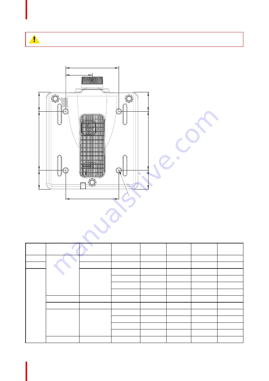
Be sure to keep at least 30 mm gap between the ceiling and the bottom of the projector.

Projector mounting holes

280.0

140.0

100.0

100.0

310.0

310.0

99.0

99.0

280.0

4 - M6 x1.0P  L10

Image A–5 Dimensions given in millimeters.

A.6 Compatibility modes

Timing table

Signal

type

Signal Format

Resolution

V sync (Hz)

HDMI1/2

DVI

HDBaseT

3G-SDI

VGA

640x350

85

V

V

V

-

640x400

85

V

V

V

-

PC

640x480

60

V

V

V

-

72

V

V

V

-

75

V

V

V

-

85

V

V

V

-

720x400

70

V

V

V

-

800x600

60

V

V

V

-

SVGA

72

V

V

V

-

75

V

V

V

-

85

V

V

V

-

120

V

V

V

-

832x624

75

V

V

V

-

Specifications

Summary of Contents for G62-W9

Page 1: ...ENABLING BRIGHT OUTCOMES User guide G62...

Page 2: ......

Page 3: ...iting of any complaints The period of guarantee begins on the date of transfer of risks in the case of special systems and software on the date of commissioning at latest 30 days after the transfer of...

Page 4: ......

Page 5: ...2 1 Main unit 22 3 Input Communication 25 3 1 Input Output I O Panel 26 3 2 Control panel 26 4 Remote Control Unit RCU 29 4 1 RCU battery installation 30 4 2 Overview of the RCU 31 4 3 Projector Addre...

Page 6: ...Projector ID 60 9 2 Remote Setup 60 9 3 Network Setup 60 9 4 Control 61 9 5 Using the web control center 62 9 6 Using RS232 command by Telnet 63 9 7 Baud Rate 63 9 8 Reset 64 10 System menu 65 10 1 L...

Page 7: ...ns for G62 W14 83 A 4 Dimensions of the G62 84 A 5 Ceiling mount 85 A 6 Compatibility modes 86 A 7 EDID table 90 B Regulatory information 93 B 1 Product compliance 94 B 2 China RoHS compliance 95 B 3...

Page 8: ...R5914653 05 G62 8...

Page 9: ...erstand and follow all safety guidelines safety instructions and warnings mentioned in this chapter before installing the G62 projector Clarification of the term G62 used in this document When referri...

Page 10: ...ndards also impose limits to the internal and external temperature rises radiation levels mechanical stability and strength enclosure construction and protection against the risk of fire Simulated sin...

Page 11: ...0 5 50 IEC 60825 1 2014 IEC 62471 5 2015 CLASS 1 RISK GROUP 3 Hazard distance 2 55 m Follow the precautions to avoid light intensity hazard NEVER look into the lens High intensity light beam Permanent...

Page 12: ...use an accessory attachment which is not recommended by the manufacturer Lightning For added protection for this video product during a lightning storm or when it is left unattended and unused for lon...

Page 13: ...ng Remove cord from the projector when storing To prevent projector damage Always remove lens cap before switching on the projector If the lens cap is not removed it may melt due to the high energy li...

Page 14: ...eplace only with the same or equivalent type recommended by the manufacturer For disposal of used batteries always consult federal state local and provincial hazardous waste disposal rules and regulat...

Page 15: ...light The extremely high brightness may cause permanent eye damage IEC 60825 1 2014 CLASS 1 LASER PRODUCT RISK GROUP 2 Complies with 21 CFR 1040 10 and 1040 11 except fro conformance as a Risk Group 2...

Page 16: ...rd distance or install the product at a height that will prevent eye exposure within the hazard distance This projector has one or several built in Class 4 laser clusters Disassembly or modification i...

Page 17: ...nce provided in IEC 62471 5 2015 section 6 6 3 5 The installer and user must understand the risk and apply protective measures based upon the hazard distance as indicated on the label and in the user...

Page 18: ...ters above the floor Horizontal clearance to the hazard distance zone shall be not less than 2 5 meters Any human access horizontally to the Hazard Zone if applicable shall be restricted by barriers I...

Page 19: ...ant for intrabeam exposure HDreflection the distance that has to be kept restrictive related to the reflected light from the rear projection screen HDdiffuse the relevant distance to be considered whi...

Page 20: ...castle Road Bracknell RG12 8PE Berkshire United Kingdom L information des consommateurs sur la r gle de tri Points de collecte sur www quefairedemesdechets fr Privil giez la r para on ou le don de vot...

Page 21: ...21 R5914653 05 G62 2 1 Main unit 22 Product overview 2...

Page 22: ...OUT HDMI 2 IN HDMI 1 IN DVI D 3G SDI IN ETHERNET USB 3D SYNC IN RS232 REMOTE IN OUT 3D SYNC Z INPUT EXIT MENU LENS FOCUS OOM ENTER 3 6 7 6 8 9 6 4 5 Image 2 2 3 LED Status Indicator 4 Input Output I O...

Page 23: ...23 R5914653 05 G62 Airflow Image 2 3 Product overview...

Page 24: ...R5914653 05 G62 24 Product overview...

Page 25: ...25 R5914653 05 G62 3 1 Input Output I O Panel 26 3 2 Control panel 26 Input Communication 3...

Page 26: ...in connector 8 Wired remote connector 9 Network connector RJ45 10 USB Type A connector 11 3D Sync out connector 12 3D Sync in connector 13 RS232 connector 3 2 Control panel Button location Z INPUT EXI...

Page 27: ...ettings INPUT Select an input source ZOOM Adjust the image size FOCUS Adjust the image focus LEFT Navigate left through the menu UP Navigate up through the menu DOWN Navigate down through the menu RIG...

Page 28: ...R5914653 05 G62 28 Input Communication...

Page 29: ...29 R5914653 05 G62 4 1 RCU battery installation 30 4 2 Overview of the RCU 31 4 3 Projector Address ID 31 4 4 Using the RCU 32 Remote Control Unit RCU 4...

Page 30: ...tents in the batteries is harmful to the skin do not touch the leakage with your bare hands directly When installing fresh batteries be sure to clean up the leakage thoroughly Under most circumstances...

Page 31: ...3 Pattern Displays test patterns 14 Brightness Set the brightness of the image 15 Contrast Set the contrast of the image 16 Lens shift H Adjust the image position horizontally 17 Lens shift V Adjust t...

Page 32: ...e sure of the following The maximum range between the remote control and the sensor is 30 m 98 4 ft Ensure to hold the remote at the following angles towards one of the IR remote control sensors horiz...

Page 33: ...33 R5914653 05 G62 30 20 30 20 Image 4 2 Remote Control Unit RCU...

Page 34: ...R5914653 05 G62 34 Remote Control Unit RCU...

Page 35: ...ring On the projector 36 5 2 Powering Off the Projector 36 This chapter assumes that the power cord and all signal cables are securely connected For detailed instructions see installation manual Power...

Page 36: ...isplay and the status LED will turn to solid green 4 Image 5 3 3 Turn on your source The projector detects the source you selected and displays the image Note If you connect multiple sources at the sa...

Page 37: ...1 3 5 4 6 2 5 Image 5 4 2 Press the POWER button or OFF key again to confirm otherwise the message disappears after 5 seconds and the projector remains on CAUTION Don t turn on the projector immediate...

Page 38: ...R5914653 05 G62 38 Powering On Off the projector...

Page 39: ...39 R5914653 05 G62 6 1 On Screen Display Menus 40 User controls 6...

Page 40: ...se arrow keys to navigate through the menus and select appropriate settings 3 Press Enter to enter the submenu or confirm a setting 4 Press Exit to return to the previous menu or exit OSD menu if at t...

Page 41: ...ns 43 7 2 Orientation 43 7 3 Aspect Ratio 44 7 4 Scale 44 7 5 Signal 44 7 6 Edge Mask 46 7 7 Geometry Correction 46 7 8 Multi Projection 48 7 9 Test Pattern 49 7 10 Freeze Screen 50 7 11 Reset 50 User...

Page 42: ...2 Overview INSTALLATION Lens Orientation Aspect Ratio Scale Signal Edge Mask Geometric Correction Multi Projection Test Pattern Freeze Screen Reset Auto Enter Select Adjust Return Image 7 1 User contr...

Page 43: ...cord from 1 to 5 to apply the lens settings Clear Memory Clear the saved lens records Lens Calibration Calibrate the lens position to return it to the center To prevent damage to the projector and the...

Page 44: ...the function settings to factory default values 7 5 Signal About signal Configure the settings to correctly project the input signals and transfer the output signals Auto Signal When Auto Signal is en...

Page 45: ...tor is displaying one of the two sources Note on backup input function Only HDMI1 HDMI2 DVI and HDBaseT inputs support the Backup Input function The 3G SDI input does not support the Backup Input func...

Page 46: ...onize the projector to the recent connected input source every time you switch the input source 7 6 Edge Mask About edge mask The edge blending function allows you to hide one or multiple edges of the...

Page 47: ...on is used to adjust the image with barrel or pincushion distortion Horizontal Correct the projected image with horizontal barrel or pincushion distortion Image 7 8 Vertical Correct the projected imag...

Page 48: ...to merge two or more adjacent images into one larger and seamless image Blend Width Set the blend pattern width Overlap Grid Number Set the blend overlap grid number Gamma Set the gamma value of the b...

Page 49: ...erformance of the projectors to have them looks as the same as possible Advanced Color Adjust the advanced color settings of the projectors to unify the color performance Lens Set up the lens of each...

Page 50: ...0 Freeze Screen About freeze screen Select to pause the display screen despite any change in the source device 7 11 Reset About reset Reset all the installation settings to factory default values User...

Page 51: ...Brightness 52 8 3 Contrast 52 8 4 Saturation 52 8 5 Tint 52 8 6 Sharpness 52 8 7 Gamma 53 8 8 White Balance 53 8 9 Advanced Color 53 8 10 Advanced Image 55 8 11 Save to User 57 8 12 Apply to User 57...

Page 52: ...am Blending Best for multiple projector installations 3D Best for playing 3D videos 2D High Speed This mode is used for displaying 2D input signal at 120Hz User Image settings saved by the user 8 2 Br...

Page 53: ...nd offset are individual controls for each RGB channels used to set grey scale The Gains calibrate the color of the dark parts and Bias calibrate the white parts Red Green Blue Gain Adjust the color o...

Page 54: ...r adjustment Hue Adjust the hue of the selected color The value reflect the number of degrees of rotation around the chromaticity diagram from the original color Increasing value indicates countercloc...

Page 55: ...e When these frames are displayed fast enough and viewed with 3D glasses synchronized with the left and right frames the viewer s brain then assemble the separate images into a single 3D image 3D Menu...

Page 56: ...seT Sub Source Select an input source for the second image The available input sources are HDMI1 HDMI2 DVI D 3G SDI and HDBaseT Swap Source Swap the main source and sub source Sub Image Size Change th...

Page 57: ...olor saturation for bright images Standard Make the images look more realistic and natural Film Improve the image details for videos Detail Improve image details in dark scenes Low Latency Use this fu...

Page 58: ...R5914653 05 G62 58 User control Image menu...

Page 59: ...62 9 1 Projector ID 60 9 2 Remote Setup 60 9 3 Network Setup 60 9 4 Control 61 9 5 Using the web control center 62 9 6 Using RS232 command by Telnet 63 9 7 Baud Rate 63 9 8 Reset 64 User controls Comm...

Page 60: ...ote receiver HDBaseT Select On to set the HDBaseT terminal as the remote receiver User Button 1 User Button 2 Assign a function to the User 1 User 2 button on the remote control It allows you to use t...

Page 61: ...control center such as powering the projector on or off and adjusting the image brightness or contrast Image 9 1 Crestron Control the projector with Crestron controller and related software Port 4179...

Page 62: ...r mobile devices System requirement To use the web control panel make sure your devices and software meet the minimum system requirements RJ45 cable CAT 5e or wireless dongle PC laptop mobile phone or...

Page 63: ...Set up direct connection between the projector and computer See block Directly connect the projector to a computer in Using the web control center page 62 2 Disable the firewall on the computer 3 Ope...

Page 64: ...R5914653 05 G62 64 9600 19200 38400 57600 115200 default 9 8 Reset About reset Reset all the communication settings to factory default values User controls Communication menu...

Page 65: ...ay 67 10 4 Logo Setup 67 10 5 Schedule 67 10 6 Standby Mode 70 10 7 Power Settings 70 10 8 Light Source Settings 70 10 9 Shutter 70 10 10 Security 71 10 11 Backlight 71 10 12 High Altitude 71 10 13 12...

Page 66: ...o Use NTP Server network based or Manual If you set the Clock Mode to Use NTP Server make sure the projector has access to the Internet Date Set a date for the projector The date format is in Year Mon...

Page 67: ...ackground color to display when no input signal is detected The available options are Blue Black White and Logo Reset Reset the menu settings to default factory values 10 4 Logo Setup About logo setup...

Page 68: ...e displays AP Mode and the projector s schedule functions are grayed out View Today View the event list scheduled for today Monday to Sunday Set up the schedule for days of a week On the Schedule menu...

Page 69: ...9 10 Power On 08 00 Event List Select Change Enter Enter Return Exit 08 01 08 01 HDMI 1 Normal Mode Page 1 2 12 13 14 15 16 Event List Select Change Enter Enter Return Exit Page 2 2 11 Image 10 3 Copy...

Page 70: ...o have the projector automatically turning on when connected to HDMI input sources Auto Power Off Set an interval timer for the projector to automatically turn off if no signal is detected within the...

Page 71: ...ector shuts down in 10 seconds Security Timer Specify the length of time the projector can be used without the password Once the timer counts to 0 the user must enter a password to use the projector T...

Page 72: ...Settings Load the previously saved user data 10 15 Reset About reset Reset the projector settings to factory default values Reset System Settings Reset the settings of the system menu to factory defau...

Page 73: ...73 R5914653 05 G62 11 1 Projector information and status 74 Information menu 11...

Page 74: ...Mode Light Source Hours Temperature Communication Projector ID Remote Code Ethernet Signal Input Signal Resolution Signal Format Pixel Clock Horz Refresh Vert Refresh Color Space Second Signal Resolu...

Page 75: ...tor Problems 76 12 2 LED indication chart 77 If you experience a problem with your projector please refer to the following information If a problem persists please contact your local re seller or serv...

Page 76: ...including the projector Image is fuzzy and blurry Press the Focus or Focus button on the remote control or control panel to adjust the image focus until it is sharp and clear To adjust focus from OSD...

Page 77: ...there are any obstructions between the remote control and the projector Check the remote batteries Make sure batteries are inserted correctly Replace the batteries if they are used up Ensure you have...

Page 78: ...Green Orange Red Green Orange Projector communication Steady Flash ing Steady Firmware upgrade Flash ing Flash ing Error Over temperature Steady Error Fan failure Flash ing Power key of the keypad is...

Page 79: ...62 A 1 Specifications for G62 W9 80 A 2 Specifications for G62 W11 81 A 3 Specifications for G62 W14 83 A 4 Dimensions of the G62 84 A 5 Ceiling mount 85 A 6 Compatibility modes 86 A 7 EDID table 90 S...

Page 80: ...hift Maximum screen size 400 Color correction Yes CLO constant light output Yes Light source Laser phosphor Light source lifetime Up to 20 000hrs Light source warranty 20 000hrs or 3 years whatever co...

Page 81: ...Shipping weight 22 6 kg Standard accessories Power cord wireless remote control Certifications CE FCC Class A cTUVUS CCC EAC KCC RCM BIS BSMI Warranty Limited 3 years parts and labor A 2 Specificatio...

Page 82: ...are tools Projector Toolset Control IR RS232 RJ45 3 5mm phone jack for wired remote Network connection 10 100 Ethernet RJ45 Output 1 x HDMI Out 1 x 3D SYNC Out 1 x DC 12V Out Power requirements 100 24...

Page 83: ...22 1 52 1 1 52 2 92 1 2 90 5 50 1 Maximum screen size 400 Optical lens shift Vertical up to 100 depending on lens Horizontal up to 30 depending on lens Motorized zoom and focus Motorized lens shift Co...

Page 84: ...e 10 to 60 C Operating humidity 10 85 RH non condensing Storage humidity 5 90 RH non condensing Dimensions WxLxH without feet 484 x 529 x 195 mm 19 1 x 20 8 x 7 7 inch with feet 484 x 529 x 206 mm 19...

Page 85: ...84 0 529 0 509 0 Image A 3 Dimensions given in millimeters Left view Image A 4 Dimensions given in millimeters A 5 Ceiling mount About ceiling mount CAUTION Be sure to use the correct screw size Screw...

Page 86: ...9 0 99 0 280 0 4 M6 x1 0P L10 Image A 5 Dimensions given in millimeters A 6 Compatibility modes Timing table Signal type Signal Format Resolution V sync Hz HDMI1 2 DVI HDBaseT 3G SDI VGA 640x350 85 V...

Page 87: ...0 V V V 75 V V V 85 V V V WXGA 1360x768 60 V V V 1366x768 60 V V V SXGA 1400x1050 60 V V V WXGA 1440x900 60 V V V 1440x900 75 V V V 1440x900 85 V V V WXGA 1600x900 60 V V V UXGA 1600x1200 50 V V V 160...

Page 88: ...V 60 V V V Side by Side 1080i 1920x1080 50 V V V 50 94 V V V 60 V V V Side by Side 1080p 1920x1080 23 98 V V V 24 V V V 59 9 V V V 60 V V V Top and Bottom 720p 1280x720 50 V V V 59 94 V V V 60 V V V T...

Page 89: ...080p Ycb Cr422 10bit 50 V 59 94 V 60 V 3GB SDI HDTV 1080p 1080p Ycb Cr422 10bit With 352M Payload ID 50 V 59 94 V 60 V 4K 3840x2160 3840x2160 24 000 V V V 25 000 V V V 30 000 V V V 50 000 V V 60 000 V...

Page 90: ...20x576i 50Hz 1024x768 60Hz 1920x1080 50Hz 1024x768 70Hz 1920x1080 24Hz 1024x768 75Hz 1440x480 60Hz 1280x1024 75Hz 1920x1080 25Hz 1152x870 75Hz HDMI 1 4 Established timing Standard timing Detail timing...

Page 91: ...800 75Hz 1920x1080 60Hz 640x480 60Hz 1280x1024 60Hz 640x480 60Hz 640x480 67Hz 1360x765 60Hz 720x480 60Hz 640x480 72Hz 800x600 120Hz 1280x1080i 60Hz 640x480 75Hz 1400x1050 60Hz 1920x1080i 60Hz 800x600...

Page 92: ...R5914653 05 G62 92 Established timing Standard timing Detail timing 3840x2160 50Hz 3840x2160 60Hz Specifications...

Page 93: ...Product compliance 94 B 2 China RoHS compliance 95 B 3 Taiwan RoHS compliance 96 B 4 Turkey RoHS compliance 97 B 5 Disposal information 97 B 6 Contact information 98 B 7 Download Product Manual 98 Re...

Page 94: ...pment generates uses and can radiate radio frequency energy and if not installed and used in accordance with the instruction manual may cause harmful interference to radio communications Operation of...

Page 95: ...ction Limit Requirements of toxic substances in Electronic Information Products Component name Hazardous substances and elements Pb Hg Cd Cr6 PBB PBDE Shell X O X O O O Motherboard X O O O O O Engine...

Page 96: ...electronic information products of Chinese Mainland B 3 Taiwan RoHS compliance Declaration of the Presence Condition of the Restricted Substances Marking Restricted substances and its chemical symbol...

Page 97: ...huriyeti AEEE Y netmeli ine Uygundur Republic of Turkey In conformity with the WEEE Regulation B 5 Disposal information Disposal Information Waste Electrical and Electronic Equipment WEEE This symbol...

Page 98: ...nvironment and human health B 6 Contact information Barco contact information Registered office address President Kennedypark 35 8500 Kortrijk Belgium Contact address Beneluxpark 21 8500 Kortrijk Belg...

Page 99: ...Compatibility modes 86 Contact address 98 Contact information 98 Contrast 52 Control 61 Control panel 26 D Date 66 Dimensions 84 Disposal 97 Battery 98 Download Product manual 98 E Edge mask 46 EDIT t...

Page 100: ...work setup 60 Notice on safety 10 O On screen display 67 On Off 35 Orientation 43 OSD 40 Overview 31 P Personal injury 12 Power 35 Power Off 36 Power On 36 Power settings 70 Product compliance 94 Prod...

Page 101: ...ications 79 G62 W11 81 G62 W9 80 G62 W14 83 Standby mode 70 System Logo setup 67 On screen display 67 System menu 65 Language 66 Schedule 67 System settings Date 66 Time 66 T Telnet RS232 command 63 T...

Page 102: ...R5914653 05 G62 102 Index...

Page 103: ......

Page 104: ...www barco com R5914653 05 2022 08 22...

Reviews: