background image

R5910887 /00

G60

10

The projection lens is an optional item, not a standard accessary in the package.

Due to the difference in applications for each country, some regions may have different accessories.

1.3 Main unit

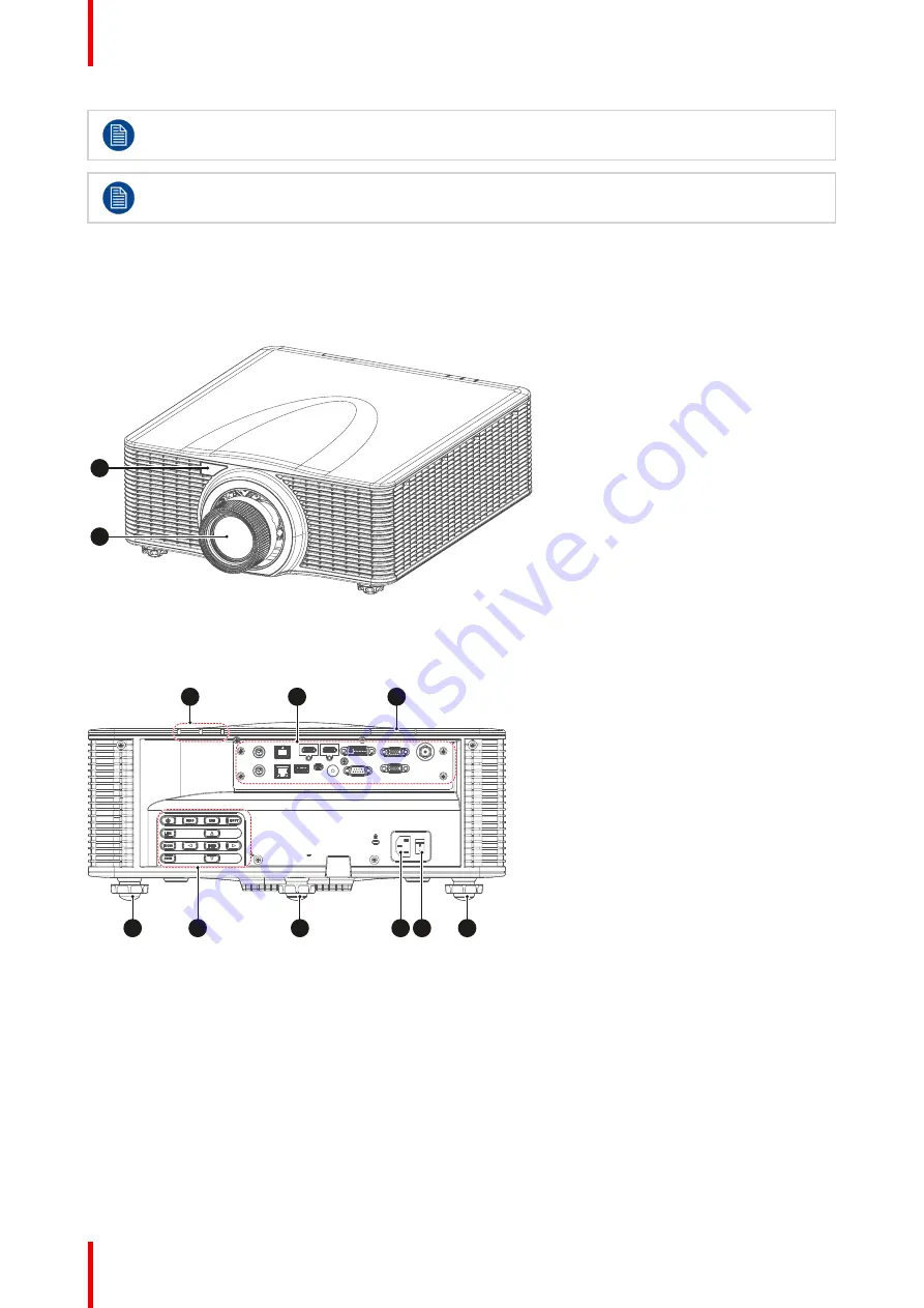
Component location

1

2

Image 1-7

1

Remote receiver (Front)

2

Projection lens

7

6

6

6

8

9

3

5

4

Image 1-8

3

LED Status Indicator

4

Input/Output (I/O) Panel

5

Remote receiver (Top)

6

Adjustable feet

7

Control panel

8

Power socket (AC100-
240V, 50-60Hz)

9

Power switch

Introduction

Summary of Contents for G60 Series

Page 1: ...ENABLING BRIGHT OUTCOMES Installation manual G60...

Page 2: ...Registered address Barco NV President Kennedypark 35 8500 Kortrijk Belgium www barco com en support www barco com Barco NV Beneluxpark 21 8500 Kortrijk Belgium www barco com en support www barco com...

Page 3: ...publication at any time without notice This publication could contain technical inaccuracies or typographical errors Changes are periodically made to the information in this publication these changes...

Page 4: ......

Page 5: ...g the projector with the power net 20 2 4 Connecting to a computer or laptop 21 2 5 Connecting to video sources 22 2 6 Ceiling mount installation 22 3 Powering On Off the projector 25 3 1 Powering On...

Page 6: ...R5910887 00 G60 6...

Page 7: ...to the optimum use of the projection system Clarification of the term G60 used in this document When referring in this document to the term G60 means that the content is applicable for following Barc...

Page 8: ...maging electronic surfaces degrading performance then it is highly advisable and desirable to have this contamination removed prior to it reaching the projectors clean air supply Devices or structures...

Page 9: ...Weight without lens G60 W7 17 4 kg G60 W8 17 4 kg G60 W10 22 7 kg 1 2 Projector package overview Box content This projector comes with all the items shown below Check to make sure your package is comp...

Page 10: ...each country some regions may have different accessories 1 3 Main unit Component location 1 2 Image 1 7 1 Remote receiver Front 2 Projection lens 7 6 6 6 8 9 3 5 4 Image 1 8 3 LED Status Indicator 4...

Page 11: ...REMOTE IN USB Type A mini USB 3G SDI RS 232 1 2 4 5 6 7 8 9 10 11 12 13 3 Image 1 10 1 3D SYNC IN 2 HDBaseTconnector 3 HDMI connector 4 DVI D input connector 5 VGA IN connector 6 3D SGI connector 7 3D...

Page 12: ...Button Function POWER Turn the projector on or off LENS Adjust lens position MENU Show the main menu on screen EXIT Return to previous menu or exit menu if at top level ENTER Confirm the settings INPU...

Page 13: ...through the menu or select the appropriate settings 10 Menu Show the main menu on the screen 11 Exit Back to previous Menu 12 Gamma Set the gamma of the image 13 PIP Set up the picture in picture PIP...

Page 14: ...s Wide zoom 0 95 1 22 1 WUXGA R9801784 G Lens Standard 1 22 1 52 1 WUXGA R9832756 G lens Long Zoom 1 52 2 92 1 WUXGA R9832778 G lens Ultra Long Zoom 2 90 5 50 1 WUXGA R9801785 G lens Ultra Short Throw...

Page 15: ...1 94 NA 1 84 2 38 2 35 2 95 2 94 5 66 5 61 10 51 1 45 1 85 100 1 35 2 15 NA 2 05 2 64 2 62 3 28 3 27 6 30 6 21 11 67 1 61 2 05 110 1 48 2 37 NA 2 26 2 91 2 89 3 62 3 60 6 93 6 82 12 82 1 78 2 26 120...

Page 16: ...R5910887 00 G60 16 Introduction...

Page 17: ...RCU battery installation Installing the lens Connecting the projector with the power net Connecting to a computer or laptop Connecting to video sources Ceiling mount installation R5910887 00 G60 Inst...

Page 18: ...es be sure to clean up the leakage thoroughly Under most circumstances you only need to point the remote control towards the screen and the IR signal would be reflected off the screen and picked up by...

Page 19: ...label TOP reference 1 is upwards oriented while inserting the lens 1 Image 2 3 3 Rotate the lens clockwise to lock the lens Image 2 4 4 Put the lens ring on the lens An audible click should be notice...

Page 20: ...OFF position reference 1 2 Connect the female side of the power cord with the power input socket of the projector reference 2 1 2 Image 2 6 3 Connect the male side of the power cord to the local power...

Page 21: ...ut cable Notes on wiring diagram The diagram shows the cables connectors that may be used to connect to various devices Due to the difference in applications for each country the accessories required...

Page 22: ...applications for each country the accessories required in some regions may be different from those shown This diagram is for illustrative purposes only and does NOT indicate that these accessories ar...

Page 23: ...887 00 G60 23 280 0 140 0 100 0 100 0 310 0 310 0 99 0 99 0 280 0 4 M6 x1 0P L10 1 Image 2 9 Dimensions given in millimeters Damage resulting from incorrect installation will void the warranty Install...

Page 24: ...R5910887 00 G60 24 Installation...

Page 25: ...that the power cord and all signal cables are securely connected For detailed instructions see installation manual Overview Powering On the projector Powering Off the Projector R5910887 00 G60 Powerin...

Page 26: ...isplay and the status LED will turn to solid green 4 Image 3 3 3 Turn on your source The projector detects the source you selected and displays the image Note If you connect multiple sources at the sa...

Page 27: ...1 3 5 4 6 2 5 Image 3 4 2 Press the POWER button or OFF key again to confirm otherwise the message disappears after 5 seconds and the projector remains on CAUTION Don t turn on the projector immediate...

Page 28: ...R5910887 00 G60 28 Powering On Off the projector...

Page 29: ...29 Overview Adjusting the projector s position Adjusting the image position on the screen R5910887 00 G60 Adjusting the projected image 4...

Page 30: ...ing on the installation Basically the projector can be positioned in On Axis or Off Axis configuration On Axis configuration means that the projector is positioned so as to have the centre of the lens...

Page 31: ...100 30 30 D L R P F U D SIDE VIEW P F 100 100 TOP VIEW P F L R 30 30 Image 4 2 D DMD F Field of view See user guide for instructions on how to shift the lens holder Screen Menu Horz Vert Position Adju...

Page 32: ...R5910887 00 G60 32 Adjusting the projected image...

Page 33: ...33 R5910887 00 G60 Communication protocols A...

Page 34: ...D P M O 8 Wall color White White C C A G W A L L 0 Gray 130 C C A G W A L L 1 Bright ness 0 100 50 B R I G Contrast 0 100 50 C O N T Sharp ness 0 10 6 S H R P Color 0 100 50 C O L R Tint 0 100 50 T I...

Page 35: ...Gain Red 1 199 H G W R Green 1 199 H G W G Blue 1 199 H G W B Reset to Default H G R T 1 Contrast En hance ment Off Off D Y B K 0 Dynamic Black D Y B K 1 Extreme Black D Y B K 2 Color Space Auto Auto...

Page 36: ...Off Auto C E M O 0 On C E M O 1 Auto C E M O 2 Rear Projec tion Off Off R E P J 0 On R E P J 1 Geomet ric Correc tion H Keystone 0 40 20 H K E S V Keystone 0 40 20 V K E S 4 Corner Top Left Horz Adju...

Page 37: ...or Green Green C N R G G R C O 0 Purple C N R G G R C O 1 Reset Yes No W R E G 1 PC Mode Off Off P C M O 0 On P C M O 1 PIP PBP PIP PBP Enable PIP Off P I B P 2 PBP P I B P 1 Off P I B P 0 Main Source...

Page 38: ...R C Signal Format M S S F Aspect Ratio M S A R Resolution M S R S Vert Refresh M S V R Horz Refresh M S H R Pixel Clock M S P C Sync Type M S S T Color Space M S C S PIP PBP When PIP PBP active Active...

Page 39: ...M 2 Test Pattern None None T P R N 0 Grid T P R N 1 White T P R N 2 Black T P R N 3 Checker board T P R N 4 Color Bars T P R N 5 Direct Power On Off Off D P O N 0 On D P O N 1 Source in Power On Off...

Page 40: ...Com mand Focus in motor go step F C S I 1 Focus out motor go step F C S O 1 Zoom Com mand Zoom in motor go step Z O M I 1 Zoom out motor go step Z O M O 1 Lens Shift Com mand Left shift up motor go st...

Page 41: ...D B T Projector Address 0 99 0 P J A D Show mes sage Off On S M S G 0 On S M S G 1 LED settings Keypad LED On On K L E D 0 Off K L E D 1 Status LED On On S L E D 0 Off S L E D 1 Warn ings Errors Only...

Page 42: ...T D I V 1 3D Format Frame Packing Depend on input signal If a HDMI source with AVINFO data existed then display 3D mode automat ically T D E N 1 Side by Side Half T D E N 2 Top and Bottom T D E N 3 Fr...

Page 43: ...2400 S P B R 1 4800 S P B R 2 9600 S P B R 3 14400 S P B R 4 19200 S P B R 5 38400 S P B R 6 57600 S P B R 7 115200 S P B R 8 Serial Port Echo Off On Off S E C G Serial Port Path RS232 RS232 S P P A...

Page 44: ...Down KEYG 35 Keystone H Left KEYG 68 Keystone H Right KEYG 69 Zoom Up KEYG 32 Keystone V Up KEYG 15 Keystone V Done KEYG 16 Zoom Down KEYG 33 Shutter AV Mute KEYG 24 Hot Key KEYG 70 Pattern KEYG 71 Co...

Page 45: ...n Progress Analog 5011 Current Source Serial 5010 Default Gateway Serial 5042 DHCP Disable Digital 5211 DHCP Enable Digital 5210 DNS Server Serial 5043 Down Digital 5152 Enter Digital 5156 Exit Digita...

Page 46: ...tal 5074 Status Message Serial 5001 Subnet Mask Serial 5041 Up Digital 5151 Warm Up Digital 5160 Warm Up Progress Analog 5010 PJ Link command list Description Command Power control instruction POWR Po...

Page 47: ...Video Mute Query PMUT Freeze FREZ1 Freeze Query FREZ Main Source MSRC Main Source Query MSRC Sub Source SSRC Sub Source Query SSRC Aspect Ratio ASPR Aspect Ratio Query ASPR Display Mode DPMO Display M...

Page 48: ...R5910887 00 G60 48 Communication protocols...

Page 49: ...Lens 18 Installation 17 Installation Requirements 8 Introduction 7 L LAN 44 Lens offset 30 Lens specifications 14 Lenses 13 M Main unit 10 O Off axis 30 On axis 30 On Off 25 P Position 30 Power 25 Po...

Page 50: ...Barco NV Beneluxpark 21 8500 Kortrijk Belgium Registered address Barco NV President Kennedypark 35 8500 Kortrijk Belgium www barco com R5910887 00 2019 01 31...

Reviews: