background image

9. GUI – System Settings

9.4.6

Service – Pixel Shift

About Pixel Shift

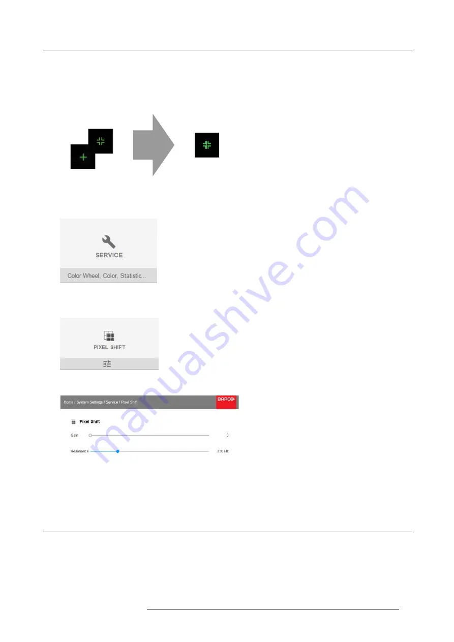
This setting allows production to

fi

ne tune the wobulator/XPR until the marker is in the ‘bullseye’. During the settings, the repetitive

on screen pattern ‘CROSS HATCH’ must be displayed. The maintenance person has to align the both following images with the
sliders available in this menu.

Image 9-24

How to

fi

ne-tuning

1. In the main menu,

System Settings

Service

.

Image 9-25

2. Enter the service code.

3. In the Service menu, select

Pixel Shift

.

Image 9-26

The Pixel Shift menu will be displayed.

Image 9-27

4. Change the values to the desired position.

-

Gain: is the amplitude of the waveform which is sent into the Wobulator. Default value: 0.65

-

Resonance (frequency) : if frequency is 0Hz the wobulator is of. High frequency means high noise. Default value: 227Hz

9.5

Reset

What can be done?

All settings and values on the projector can be reset to its default values. This can be done for one or more settings separately, or
all settings together (factory reset).

Default settings

The following settings are default settings:

R5906852 F80 SERIES 21/09/2017

67

Summary of Contents for F80-Q7

Page 1: ...F80 series User Manual R5906852 00 21 09 2017...

Page 2: ...56 23 32 11 Fax 32 56 26 22 62 Support www barco com en support Visit us at the web www barco com Barco Fredrikstad AS Habornveien 53 N 1630 Gamle Fredrikstad Norway Phone 47 6930 4550 Fax 47 6930 458...

Page 3: ...mage and also damage attributed to the operation of software as well as to other services provided by Barco being a component of the system or independent service will be deemed invalid provided the d...

Page 4: ......

Page 5: ...ing Started 23 4 1 Functionality overview 23 4 2 Power modes 24 4 3 Power mode transitions 25 4 3 1 General 25 4 3 2 Power on projector 25 4 3 3 Going from READY to ON 26 4 3 4 Going from ON to READY...

Page 6: ...bration 65 9 4 5 Lens features 66 9 4 6 Service Pixel Shift 67 9 5 Reset 67 10 Status menu 71 10 1 Status menu overview 71 11 Maintenance 73 11 1 Cleaning the lens 73 11 2 Cleaning the exterior of the...

Page 7: ...e equipment to the user even when the equipment s normal operation fails Notice on optical radiation This projector embeds extremely high brightness radiance lasers this laser light is processed throu...

Page 8: ...operated from a mono phase AC power source This apparatus must be grounded earthed via the supplied 3 conductor AC power cable If none of the supplied power cables are the correct one consult your de...

Page 9: ...uit leaks switch off the device and contact qualified service personnel The liquid is not for household use Keep out of reach of children Harmful by oral intake Avoid exposure to pregnant women Avoid...

Page 10: ...rs Use a damp cloth for cleaning Never use strong solvents such as thinner or benzine or abrasive cleaners since these will damage the cabinet Stubborn stains may be removed with a cloth lightly dampe...

Page 11: ...HARACTERISTICS AUTHORIZED BY VARIANCE NUMBER 2017 V 4837 EFFECTIVE September 13 2017 This projector may become RG3 when an interchangeable lens with throw ratio greater than 3 5 is installed Refer to...

Page 12: ...he beam shall be permitted For RG3 operators shall control access to the beam within the hazard distance or install the product at a height that will prevent eye exposure within the hazard distance Th...

Page 13: ...not extend into the audience area unless the beam is at least 2 0 meter above the floor level In non cinema environments where unrestrained behavior is reasonably foreseeable the minimum separation h...

Page 14: ...two areas should be considered the restricted enclosed projection area RA and the observation area TH RA TH sw PD HDDIFFUSE sw RZ sw sw PR HD REFLECTION RESTRICTED AREA RESTRICTED AREA Image 1 3 RA R...

Page 15: ...tion screen To determine the HD distance for the used lens and projector model see graphs in chapter HD in function of the lens Throw Ratio TR page 11 HDreflection 25 HD PD The light emitted from the...

Page 16: ...1 Safety 12 R5906852 F80 SERIES 21 09 2017...

Page 17: ...s first How to install 1 Push the battery cover tab with the fingernail a little backwards 1 and pull at the same time the cover upwards 2 1 2 Image 2 1 2 Insert the two AA size batteries making sure...

Page 18: ...ards Image 2 4 2 Connect a cable with XLR plug into the XLR connector of the RCU 3 Connect the other end of the cable with the XLR input of the projector 2 3 Remote control on off button Purpose of th...

Page 19: ...2 Remote Control Unit 1 Image 2 5 R5906852 F80 SERIES 21 09 2017 15...

Page 20: ...2 Remote Control Unit 16 R5906852 F80 SERIES 21 09 2017...

Page 21: ...ns are located at the back of the projector 1 3 6 8 2 4 5 7 9 11 10 12 Image 3 2 Nb Name Pcs Description Purpose 1 DMX IN OUT 2 DMX 512 input DMX 512 output For Projector Control 2 RS 232 1 9 pin DB9...

Page 22: ...put If these outputs are loaded too heavy there is a risk that the projector will go in reset mode and restart This causes no damage to the projector but is an undesirable response This will also happ...

Page 23: ...BR2 Supported Link Rate RBR HBR1 HBR2 Scan format Progressive Max input data resolution 4096x2160 60Hz 4K Max Bit depth 8 10 12 bit EDID Supported HDCP Supported 3 4 3 HDMI 2 0 Specifications Regardin...

Page 24: ...resolution supported 1920x1200 60Hz WUXGA 60Hz HDCP Pass Through Yes from Source to Projector IR Extension Not Supported RS 232 Extension Not Supported 10 100Mbps Ethernet Pass Through Not Supported F...

Page 25: ...ector is ON Standby button Blinking RED Error condition Off no color Projector is OFF starts up or is in Standby mode Solid WHITE Projector is ON shutter is open Shutter button Solid RED Projector is...

Page 26: ...3 Input Communication 22 R5906852 F80 SERIES 21 09 2017...

Page 27: ...ontrol are switching between stand by and operational mode switching to pause blanked picture full power for immediate restarting direct access to all connected sources Overview Functionality overview...

Page 28: ...trol is a full feature wireless remote control powered by two 2 standard AA batteries The battery com partment is on the back side of the remote control The remote control is backlit for use in dark e...

Page 29: ...and local power up button are supported 4 3 Power mode transitions 4 3 1 General Transition Diagram This diagram shows all modes available on the projector unplug ON READY ECO and the actions necessa...

Page 30: ...ector is in READY thePower on off button will be lit WHITE 4 3 5 Going from READY to ECO standby Description If ECO Standby mode is enabled in the service menu refer to the section GUI system settings...

Page 31: ...ct of burn in and increase the projector lifetime CAUTION Never switch off the projector by means of unplugging mains cord or by cut down of mains power Barco advises to keep the projector always powe...

Page 32: ...eflective screen Hardwired to the mini jack input 1 Plug one end of the remote cable in the connector on the front side 3 5mm mini jack of the RCU 2 Plug the other end in the connector on the communic...

Page 33: ...puter Therefore each projector has its own address Set up an individual Projector Address The set up of a projector address can be done via the software Projector controlling Every projector requires...

Page 34: ...seconds Note That address can be any value between 0 and 31 Tip A few examples To enter address 3 press 3 digit button on the RCU to set the RCU s address to 3 and wait until the button pressed indica...

Page 35: ...lection 1 Press the Test pattern button on the remote control or local keypad P P Image 4 8 A first test pattern will be displayed 2 Press as may times on that button until the desired pattern is disp...

Page 36: ...4 Getting Started 32 R5906852 F80 SERIES 21 09 2017...

Page 37: ...ach main menu contains submenus The OSD can be disabled by pressing the OSD on off button Image 5 1 Home menu The projector s software platform uses access levels what each user can do A standard user...

Page 38: ...ow keys to move the bar scale slider up or down on the value line For a bar scale 0 9 each step will equal 10 of the total value To enter the value as a direct number press OK input the digit s and th...

Page 39: ...tern from the list You can select one of the following Patterns test patterns Refresh Native Black You can select one of the following Internal test patterns Aspect ANSI Lumen Checker Board Focus Cros...

Page 40: ...5 Graphic User Interface GUI 36 R5906852 F80 SERIES 21 09 2017...

Page 41: ...Select Source menu is displayed with the actual available sources filled out 3 Select the desired input 6 2 Connector Settings How to configure the connector 1 Press Menu to activate the menus and sel...

Page 42: ...be displayed All default values are Auto Image 6 4 5 To apply a limit on the used color space select one of the other values in Color space 6 To apply a limit on the used signal range select one of th...

Page 43: ...gnal main and PiP window together of the projected image How to set up Contrast 1 In the main menu select Image Contrast Image 7 1 Image menu Contrast 2 Use the or key to change the contrast enhanceme...

Page 44: ...ached adjustable between 1 and 1 Image 7 6 Saturation slider 3 Use the or key to select Brightness or Contrast Or go to Home Image and select Brightness or Contrast 7 2 P7 Realcolor Purpose When blend...

Page 45: ...ates The white point is specified using an x y coordinate in the CIE 1931 Chart Temperature Configure the white point via a color temperature slider The white point is specified on a Kelvin scale betw...

Page 46: ...7 GUI Image Image 7 9 The PQ menu is displayed Image 7 10 2 Select the desired Unit nits or foot lambert 3 Enter the Screen luminance either in nit or foot lambert 42 R5906852 F80 SERIES 21 09 2017...

Page 47: ...Please refer to the lens calibration section in System Settings Lens Calibration menu Vertical and Horizontal Shift 1 To change the position of the projected image select Installation Lens Shift Imag...

Page 48: ...elect the desired projection position and press OK button to activate 8 3 Warping 8 3 1 About warping Overview Image warping is the process of digitally manipulating an image to compensate for the dis...

Page 49: ...e information but also the black bars If we want to position e g the active left top corner exactly on the screen using 4 corner warp then it is very hard to do that as we are moving the black left to...

Page 50: ...a visual tool showing the result of the adjusted outline 4 Click Apply 8 3 4 Warping 4 corners adjustment About 4 Corners adjustment 4 corner adjustment is typically used when the mechanical installat...

Page 51: ...corner using the arrow keys Tip A red border corner will be projected along with the current image The border is a visual aid showing the result of the warped corners 5 Repeat from step 3 for each cor...

Page 52: ...n menu Warp 2 In the Warp menu select Bow Image 8 16 Warp menu Bow A check symbol at the bottom right corner indicates that the bow function is activated 3 To enable Bow correction make sure the Bow s...

Page 53: ...e projector This is a time saving option when multiple projectors need an identical Warp configuration To upload or download warp files you can use Projector Toolset or upload download the warp grid i...

Page 54: ...tion between the channels Image blending gives the appear ance of a single view thus achieving realistic immersion for the majority of wide screen applications The principle is that the light intensit...

Page 55: ...end zones 1 In the main menu select Installation Blend Blend Zones Image 8 23 Blend menu Zones The Blend zones menu is displayed Image 8 24 Blend Zone menu 2 To enable blending put the switch to the r...

Page 56: ...dth The basic principle is that the overlap setup in the source shall correspond with the blend width setup for the projector That means that if the overlap zone for the source is set to 500 pixels th...

Page 57: ...ultiple projectors will project on the same screen area The size of the black level area is calculated automatically from the blend zones This is done by using the start position and size of each edge...

Page 58: ...load a custom Black Level adjustment file in xml format to from the projector To upload or download Black Level adjustment files you can use Projector Toolset or upload download the Black Level adjust...

Page 59: ...figurationin the GUI you can also upload or download a custom Blend configuration file in xml format to from the projector This is a time saving option when multiple projectors need an identical blend...

Page 60: ...configuration file 1 In the main menu select Installation Blend Image 8 35 Installation menu Blend 2 In the Blend menu select Blend Files Image 8 36 Blend menu Blend Files The Blend Files menu is dis...

Page 61: ...compatible battery operated shutter glasses The options on the projector allow you to fine tune the 3D settings accordingly to the specifications of the 3D emitter If a 3D emitter is used that radiate...

Page 62: ...stallation 2 Select the desired the stereo Dark Time 3 Use the slider to set the desired stereo sync delay 4 If necessary to invert the stereo sync click the Swap Eye option 58 R5906852 F80 SERIES 21...

Page 63: ...tion with the internet Subnet mask A number that is used to identify a subnetwork so that IP addresses can be shared on a local area network Default Gateway A router that serves as an entry point into...

Page 64: ...o enable Automatic put the switch to the right The color of the switch becomes blue An automatic IP is assigned When connected it is indicated with the connection symbol and the indication Connected 3...

Page 65: ...There are two options light default or dark How to select a different interface theme 1 In the main menu select System Settings Themes Image 9 5 System Settings Menu Themes 2 In the themes menu select...

Page 66: ...e with the numeric keys and select OK and click OK on to confirm Otherwise select DISCARD and click OK to return to the System Settings menu Overview Service Color Wheel Service Color Service Statisti...

Page 67: ...nless parts of the optical path have been replaced due to servicing If you need to change the native colors on the device make sure to also perform a P7 calibration using the Projector Toolset and a c...

Page 68: ...4 3 Service Statistics What can be seen The statistics screen shows the general information about the projector The following items will be displayed Laser runtime Laser Strikes Projector Runtime Sys...

Page 69: ...ettings Service Image 9 18 2 Enter the service code 3 In the Service menu select Lens Calibration Image 9 19 System Settings menu Lens Calibration The Lens Calibration menu is displayed Image 9 20 Len...

Page 70: ...sible How to enable disable 1 In the main menu System Settings Service Image 9 21 2 Enter the service code 3 In the Service menu select Lens features Image 9 22 Service menu lens features The Lens fea...

Page 71: ...vice code 3 In the Service menu select Pixel Shift Image 9 26 The Pixel Shift menu will be displayed Image 9 27 4 Change the values to the desired position Gain is the amplitude of the waveform which...

Page 72: ...able Front ImageResolution Output Resolution 4K UHD ImageStereo Sync delay 0 s Swap eye Off Dark time lowest value available UserInterface Theme Light Optics High Contrast Off Illumination Power 100 N...

Page 73: ...displayed Image 9 29 Reset menu 2 Navigate to the checkbox next to the settings that need to be reset and press OK Multiple selection are possible 3 Select RESET and press OK to reset all selected set...

Page 74: ...9 GUI System Settings 70 R5906852 F80 SERIES 21 09 2017...

Page 75: ...tion Product Displays active product information Article number Projector article part number Serial number Projector serial number Firmware Projector software package version Model name Projector mod...

Page 76: ...10 Status menu 72 R5906852 F80 SERIES 21 09 2017...

Page 77: ...d dirt into the coating 3 Use a dry lens cleaning cloth to remove left liquid or stripes Polish with small circles 4 If there are still fingerprints on the surface wipe them off with lens cleaner toge...

Page 78: ...11 Maintenance 74 R5906852 F80 SERIES 21 09 2017...

Page 79: ...rt SDI DMX Power requirements 100 240V 50 60Hz Power consumption 700 W nominal 850 W maximum Noise level typical at 25 C 77 F 35 dB A Dimensions WxLxH 480 x 680 x 227 mm 18 9 x 26 7 x 8 9 in Weight 25...

Page 80: ...16 10 Optical lens shift Motorized zoom focus vertical and horizontal shift Throw Ratio 0 85 1 06 1 06 1 43 1 43 2 12 2 12 3 18 and compatible with FLD FLD series with adapter Light source Laser phosp...

Page 81: ...Up to 40 000 hours Orientation 360 rotation no restrictions Inputs HDMI DVI HDBaseT DisplayPort SDI DMX Power requirements 100 240V 50 60Hz Power consumption 950 W nominal 1100 W maximum Noise level t...

Page 82: ...s A 6 Technical Regulations Certificates Image A 2 EAC mark 10 Image A 3 Rohs Image A 4 CE mark Image A 5 Nemco mark 60950 Image A 6 CCC mark Image A 7 FCC label Image A 8 RCM mark 78 R5906852 F80 SER...

Page 83: ...lues of lead Pb mercury Hg or cadmium Cd these chemical symbols will appear below the crossed out wheeled bin symbol By participating in separate collection of batteries you will help to ensure proper...

Page 84: ...at least one of the homogeneous materials used for this part is above the limit requirement in GB T 26572 EIP EFUP Barco EFUP 10 All Electronic Information Products EIP that are sold within Chinese M...

Page 85: ...lue of presence condition 2 O Note 2 O indicates that the percentage content of the restricted substance does not exceed the percentage of reference value of presence 3 Note 3 The indicates that the r...

Page 86: ...s regional offices via the contact information given on Barco s web site www barco com Made in information The made in country is indicated on the product ID label on the product itself Production dat...

Reviews: