6. GUI orientation
6.8
Con
fi
guration Menu > Device area
General
This part of the System con
fi
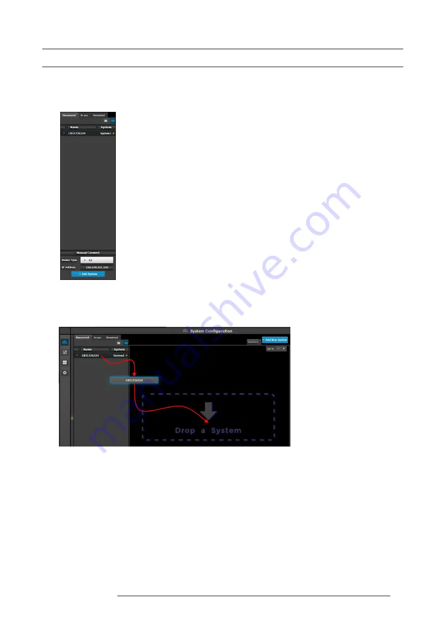
guration page allows to list devices available on the local network and identify the devices.
Description
There are 3 tabs in this section:
•
Devices in use: Lists the devices in the selected System. If multiple Systems are present, the list
will display the devices in the selected system
•
Discovered: Lists the discovered devices on the local network regardless of the selected System.
•
Simulated: List of simulated devices we support will be shown, regardless of the selected System.
This is post release 1 feature. Note: When this tab is selected, the Event Master Control Software
will continuously send a UDP broadcast over the network to locate devices (every 5 seconds)
Next to the device name an LED indicates the status of the unit:
•
Yellow : Found in network but not assigned
•
Green: Assigned and currently has an open or active communication port
•
Red: Assigned but currently has errors trying to communicate (heart beat communication failure,
TCP connection dropped, etc. )
•
Orange: There is a con
fi
guration error with the unit:
- Input / Output cards not right justi
fi
ed. Refer to the corresponding section below of the card
placement rules and error color code.
- Input / Output con
fi
guration mismatch with the actual unit. Refer to the corresponding
con
fi
guration section of the card placement rules and error color code.
How to add a device into the selected system?
1. Left click on the device to be assigned to the selected system.
2. Drag it to the System diagram area.
Image 6-7
How to manually add a device into the selected system?
To manually add a device, use the “Manual Add” section.
1. Select the type of device from the drop down (showing list of supported devices).
2. Enter the IP address.
3. Press the “Add” button.
R5905948 E2 12/12/2014
77
Summary of Contents for Event Master E2
Page 1: ...E2 User s guide R5905948 00 12 12 2014...
Page 8: ...Table of contents 4 R5905948 E2 12 12 2014...
Page 16: ...2 Safety 12 R5905948 E2 12 12 2014...
Page 32: ...3 General 28 R5905948 E2 12 12 2014...
Page 82: ...6 GUI orientation Image 6 8 78 R5905948 E2 12 12 2014...
Page 94: ...6 GUI orientation Image 6 20 90 R5905948 E2 12 12 2014...
Page 115: ...6 GUI orientation Image 6 37 Thumbnail view Image 6 38 R5905948 E2 12 12 2014 111...
Page 186: ...7 System Setup 182 R5905948 E2 12 12 2014...
Page 192: ...8 Updating firmware 188 R5905948 E2 12 12 2014...
Page 196: ...9 General operation example Image 9 3 192 R5905948 E2 12 12 2014...
Page 213: ...9 General operation example Image 9 25 R5905948 E2 12 12 2014 209...
Page 216: ...9 General operation example 212 R5905948 E2 12 12 2014...
Page 220: ...10 Maintenance 10 2 Process Overview Flow chart Image 10 2 216 R5905948 E2 12 12 2014...
Page 281: ...10 Maintenance Disregard the heatsink from the spare kit R5905948 E2 12 12 2014 277...
Page 282: ...10 Maintenance 278 R5905948 E2 12 12 2014...
Page 288: ...11 Environmental information 284 R5905948 E2 12 12 2014...
Page 298: ...B Remote Control Protocol 294 R5905948 E2 12 12 2014...
Page 299: ...C Troubleshooting C TROUBLESHOOTING R5905948 E2 12 12 2014 295...
Page 300: ...C Troubleshooting 296 R5905948 E2 12 12 2014...


