6. GUI orientation
6.5
Screen layout presentation
General
The user interface is organized around a
Menu Navigation bar
at the left of the screen and a
Working area
in the rest of the screen.
The layout of the screens is similar throughout the GUI.
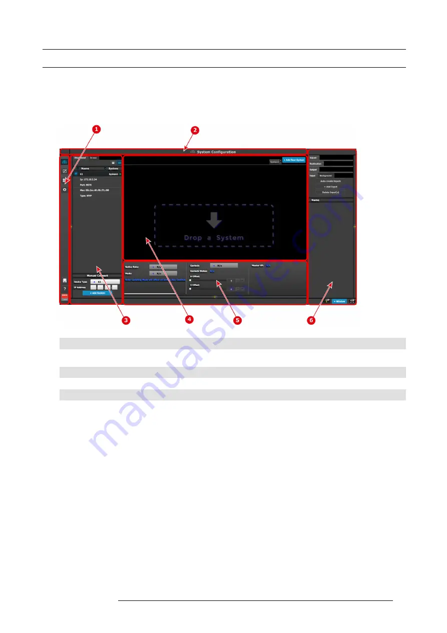
In order to explain the layout, we will examine the start-up screen of the
Con
fi
guration Menu
and describe it’s the different compo-
nents. The screens for the other menus follow the same structure and
fl
ow.
Image 6-1
1
Menu navigation bar
2
Title bar
3
Selection area
4
Diagram area
5
Modi
fi
er area
6
Con
fi
guration area
Menu navigation bar
On the far left hand side of the screen is the
Menu Navigation bar
that allows users to navigate between the different screens and
save or restore system con
fi
gurations. This area of the screen is always visible and remains unchanged. The available buttons on
the
Menu Navigation bar
are:
•
System Con
fi
guration
: allows access to
System Con
fi
guration Menu
.
•
Programming
: allows access to
Programming Menu
.
•
Multiviewer
: allow access to
Multiviewer Menu
.
•
E2 built-in web page.
•
System Save and Restore.
Title bar
On the top of the working area a title bar indicates the name of the selected page (e.g. System con
fi
guration).
Selection area
The selection area allows the users to select the System, Device or inputs that will be used.
Diagram area
In the middle, is the Diagram area where the system, Screens and Multiviewer are represented graphically.
R5905948 E2 12/12/2014
73
Summary of Contents for Event Master E2
Page 1: ...E2 User s guide R5905948 00 12 12 2014...
Page 8: ...Table of contents 4 R5905948 E2 12 12 2014...
Page 16: ...2 Safety 12 R5905948 E2 12 12 2014...
Page 32: ...3 General 28 R5905948 E2 12 12 2014...
Page 82: ...6 GUI orientation Image 6 8 78 R5905948 E2 12 12 2014...
Page 94: ...6 GUI orientation Image 6 20 90 R5905948 E2 12 12 2014...
Page 115: ...6 GUI orientation Image 6 37 Thumbnail view Image 6 38 R5905948 E2 12 12 2014 111...
Page 186: ...7 System Setup 182 R5905948 E2 12 12 2014...
Page 192: ...8 Updating firmware 188 R5905948 E2 12 12 2014...
Page 196: ...9 General operation example Image 9 3 192 R5905948 E2 12 12 2014...
Page 213: ...9 General operation example Image 9 25 R5905948 E2 12 12 2014 209...
Page 216: ...9 General operation example 212 R5905948 E2 12 12 2014...
Page 220: ...10 Maintenance 10 2 Process Overview Flow chart Image 10 2 216 R5905948 E2 12 12 2014...
Page 281: ...10 Maintenance Disregard the heatsink from the spare kit R5905948 E2 12 12 2014 277...
Page 282: ...10 Maintenance 278 R5905948 E2 12 12 2014...
Page 288: ...11 Environmental information 284 R5905948 E2 12 12 2014...
Page 298: ...B Remote Control Protocol 294 R5905948 E2 12 12 2014...
Page 299: ...C Troubleshooting C TROUBLESHOOTING R5905948 E2 12 12 2014 295...
Page 300: ...C Troubleshooting 296 R5905948 E2 12 12 2014...


