6. GUI orientation
It is possible that after the unit is turned on, the hardware con
fi
guration can be altered making certain Destinations to have invalid
Output con
fi
gurations.
In this case the Destination in the System Diagram becomes grey and adjustment are disabled. In this case the destination needs
to be deleted and new one created to re
fl
ect the existing output con
fi
guration.
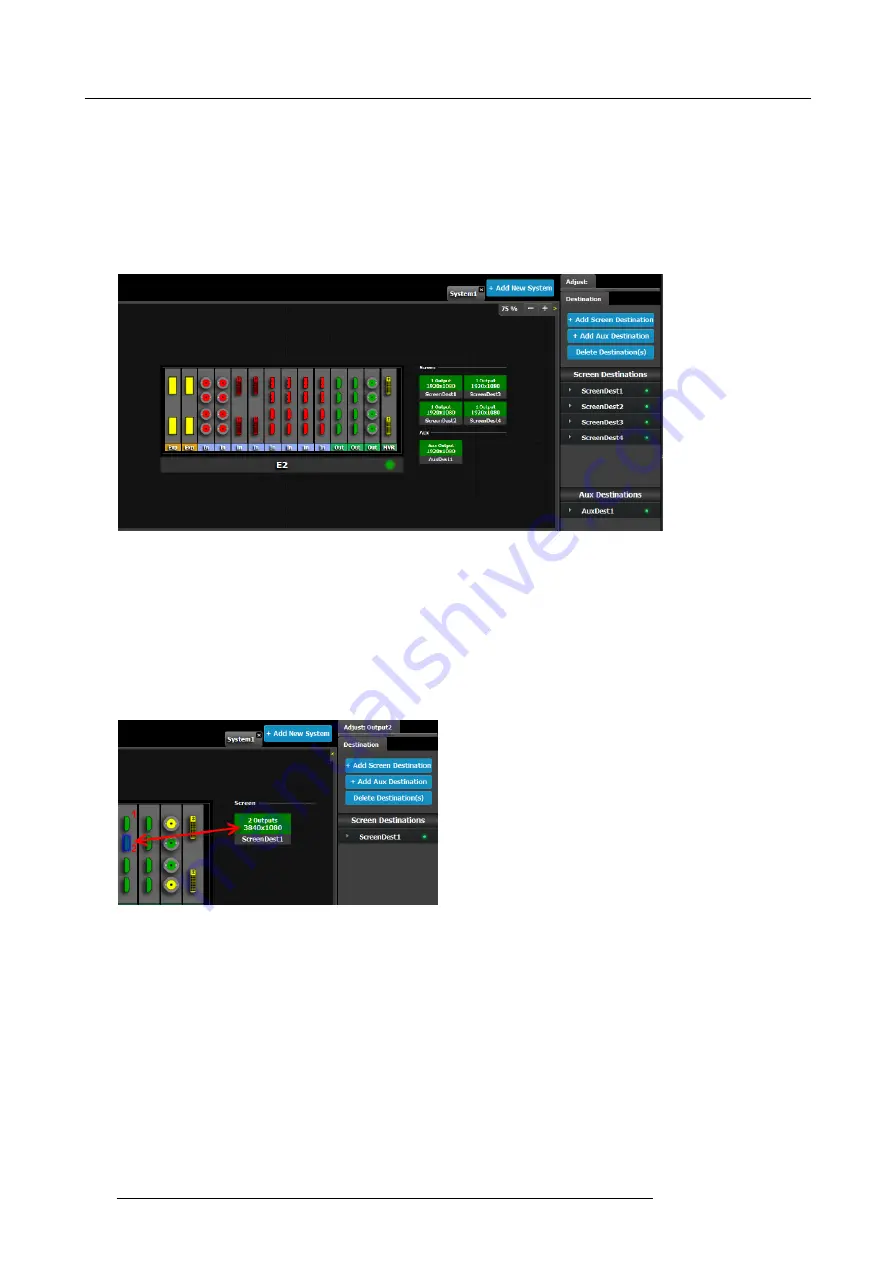
How to add Destination
To assign an output con
fi
guration to a destination, select the output con
fi
guration (output Tab) and then click on the
Add Screen
Destination
or the
Add Aux Destination button
(Destination Tab). These buttons are enabled (highlighted in blue) as long as there
are unassigned output con
fi
gurations.
Image 6-27
If the
Add destination
button is pressed without selecting an output con
fi
guration, the software will automatically assign the
fi
rst
unassigned output con
fi
guration (from left most output card) to a destination. The output con
fi
guration format is copied to the desti-
nation output format.
New
Screen
or
Aux
destinations can be added as long as there are unassigned output con
fi
gurations to destinations.
Alternatively, you assign outputs to destinations by dragging them into the output con
fi
guration the Destination block. In the example
below, the output 1 was assigned to ScreenDest1 and the destination format was set to 1920x1080 re
fl
ecting the format of output1.
When output 2 is dragged into the same destination, then the format changes to 3820x1080 re
fl
ecting a 2x1 setup. When outputs
are dragged into a destination in this matter, the software assumes it is a horizontal setup with 0 pixel overlap. The overlap can
be modi
fi
ed in the … menu. If a vertical setup is desired, then the output con
fi
guration needs to be setup as such in the output
con
fi
guration menus.
Image 6-28
How to delete Destination
1. Click on the
Delete Destination(s)
button
The
Delete Destination(s)
button is replaced by the
Delete Selected
button (highlighted in red) and the E2 diagram is greyed
out, except the area dedicated to destinations (Screen and Aux).
2. Click on destination in the graphical area.
100
R5905948 E2 12/12/2014
Summary of Contents for Event Master E2
Page 1: ...E2 User s guide R5905948 00 12 12 2014...
Page 8: ...Table of contents 4 R5905948 E2 12 12 2014...
Page 16: ...2 Safety 12 R5905948 E2 12 12 2014...
Page 32: ...3 General 28 R5905948 E2 12 12 2014...
Page 82: ...6 GUI orientation Image 6 8 78 R5905948 E2 12 12 2014...
Page 94: ...6 GUI orientation Image 6 20 90 R5905948 E2 12 12 2014...
Page 115: ...6 GUI orientation Image 6 37 Thumbnail view Image 6 38 R5905948 E2 12 12 2014 111...
Page 186: ...7 System Setup 182 R5905948 E2 12 12 2014...
Page 192: ...8 Updating firmware 188 R5905948 E2 12 12 2014...
Page 196: ...9 General operation example Image 9 3 192 R5905948 E2 12 12 2014...
Page 213: ...9 General operation example Image 9 25 R5905948 E2 12 12 2014 209...
Page 216: ...9 General operation example 212 R5905948 E2 12 12 2014...
Page 220: ...10 Maintenance 10 2 Process Overview Flow chart Image 10 2 216 R5905948 E2 12 12 2014...
Page 281: ...10 Maintenance Disregard the heatsink from the spare kit R5905948 E2 12 12 2014 277...
Page 282: ...10 Maintenance 278 R5905948 E2 12 12 2014...
Page 288: ...11 Environmental information 284 R5905948 E2 12 12 2014...
Page 298: ...B Remote Control Protocol 294 R5905948 E2 12 12 2014...
Page 299: ...C Troubleshooting C TROUBLESHOOTING R5905948 E2 12 12 2014 295...
Page 300: ...C Troubleshooting 296 R5905948 E2 12 12 2014...


