background image

6. Source Connections

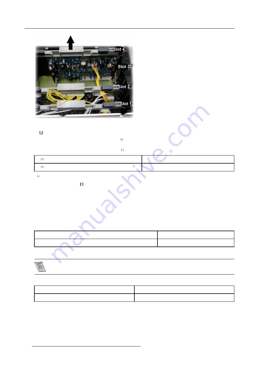
Image 6-12
Extract the module out of the main frame

75

Termination Resistors

In case of chaining (loop-through) the projectors, the 75

line termination resistors must be removed from the second RGB Input

Module when the projector is NOT the last unit in the chain.

In case of a stand-alone projector, do not remove the 75

Termination Resistors.

75

Resisters on module

Line Terminated

75

Resisters removed

Line Not Terminated

Table 6-7
75

Termination Resistors

How to remove the 75

Termination Resistors

1. Turn Off the projector and unplug the projector power cord.

2. Remove the protection plate on top of the electric block.

3.

Remove the RGB Input Module from the main frame.

4. Unsolder and remove the resistors.

Blue in Green Switch

Blue characters are difficult to read, therefore the blue text will be displayed as cyan so that the readability becomes better.

Blue in Green Switch in the ON position

Blue in Green Active

Blue in Green Switch in the OFF position

Blue in Green Disabled

Table 6-8
Blue in Green Switch

Leaving the switch in the ON position will result in abnormal color balance of the projected image.

Force Negative Sync Switch

Force Negative Sync Switch in the ON position

The Sync Pulses must be Negative

Force Negative Sync Switch in the OFF position

The Sync Polarity will be Automatically Detected

42

R5976354 BARCOREALITY 908 SPLIT PACK 10092002

Summary of Contents for BarcoReality 908

Page 1: ...SIMULATION PRODUCTS BARCOREALITY 908 SPLIT PACK R9040080 INSTALLATION MANUAL 10092002 R5976354 00...

Page 2: ...ne 1 937 372 7579 Fax 1 937 372 8645 E mail eis barco com Visit us at the web www eis barco com Barco nv Simulation Products Noordlaan 5 B 8520 Kuurne Phone 32 56 36 82 11 Fax 32 56 36 84 86 E mail in...

Page 3: ...rovements and or changes to the product s and or the program s described in this publication at any time without notice This publication could contain technical inaccuracies or typographical errors Ch...

Page 4: ......

Page 5: ...ordlaan 5 B 8520 Kuurne Phone 32 56 36 82 11 Fax 32 56 36 84 86 E mail info barco com Web www barco com From Date Please correct the following points in this documentation R5976354 00 page wrong corre...

Page 6: ......

Page 7: ...t 3 38 6 5 RGB Analog Source with Composite Sync to Port 4 5 43 6 6 Component Video Source to Port 4 5 43 6 7 RGB Analog Source with Tri Level Sync to Port 4 5 Optional 43 6 8 Component Video Source w...

Page 8: ...Table of contents 2 R5976354 BARCOREALITY 908 SPLIT PACK 10092002...

Page 9: ...is manual thoroughly and retain it for future reference Installation and preliminary adjustments should be performed by qualified BARCO personnel or by authorized BARCO service dealers Owner s Record...

Page 10: ...nel before resuming operations Lightning For added protection for this video product during a lightning storm or when it is left unattended and unused for long periods of time unplug it from the wall...

Page 11: ...ts which have the same characteristics as the BARCO original part Unauthorized substitutions may result in degraded performance and reliability fire electric shock or other hazards Unauthorized substi...

Page 12: ...1 Safety Instructions 6 R5976354 BARCOREALITY 908 SPLIT PACK 10092002...

Page 13: ...and place it on a table Image 2 1 Save the original shipping carton and packing material they will be necessary if you ever have to ship your projector For maximum protection repack your projector as...

Page 14: ...in mm inch Image 2 2 Electronic Block rear View Dimensions Image 2 3 Electronic Block bottom view dimensions Image 2 4 Electronic Block front view dimensions Image 2 5 Electronic block right view dime...

Page 15: ...Image 2 6 Electronic Block right view dimensions Image 2 7 Electronic Block top view dimensions Optical Block dimensions in mm inch Image 2 8 Optical Block bottom view dimensions R5976354 BARCOREALITY...

Page 16: ...ge 2 9 Optical Block front view dimensions Image 2 10 Optical Block front view dimensions Image 2 11 Optical Block left view dimensions Image 2 12 Optical Block left view dimensions 10 R5976354 BARCOR...

Page 17: ...2 Packaging and Dimensions Image 2 13 Optical Block top view dimensions R5976354 BARCOREALITY 908 SPLIT PACK 10092002 11...

Page 18: ...2 Packaging and Dimensions 12 R5976354 BARCOREALITY 908 SPLIT PACK 10092002...

Page 19: ...ojectors optics as these will degrade optical coatings and damage sensitive optoelectronics components Failure to take suitable precautions to protect the projector from the effects of persistent and...

Page 20: ...sible A high gain screen will provide a brighter picture but reduce the viewing angle For more information about screens contact your local screen supplier Lens Type Image Sizing Following lens types...

Page 21: ...ject images in four different configurations Front table Rear table Front ceiling Rear ceiling Image 3 3 Possible Configurations Positioning the projector The projector should be installed perpendicul...

Page 22: ...3 Installation Guidelines Image 3 4 Front Table positioning 16 R5976354 BARCOREALITY 908 SPLIT PACK 10092002...

Page 23: ...3 Installation Guidelines Image 3 5 Front Ceiling positioning R5976354 BARCOREALITY 908 SPLIT PACK 10092002 17...

Page 24: ...Remove the battery cover on the backside by pushing the handle a little towards the bottom of the RCU 2 Lift up the top side of the cover at the same time 3 Insert the batteries as indicated in the RC...

Page 25: ...e setup for common address zero To change the common address of the RCU contact a BARCO service center If it is necessary to program the projector address into the RCU see chapter Getting Started Proj...

Page 26: ...3 Installation Guidelines 20 R5976354 BARCOREALITY 908 SPLIT PACK 10092002...

Page 27: ...lock image 4 3 4 Remove the protection plate on the back image 4 4 5 Loosen the 4 indicated screws on each side of the optical block image 4 5 6 Loosen the 2 indicated screws on top of the optical blo...

Page 28: ...e cable UNDER the picture tube unit and connect this cable to the EHT connection on the EHT block image 4 11 5 Connect the RGB cables to the BNC connectors on the back of the optical block the cables...

Page 29: ...n Setup Image 4 10 Tighten the fastener ring so that the cable tube is secured to the block Image 4 11 Connecting the EHT cable Image 4 12 Connecting the RGB cables R5976354 BARCOREALITY 908 SPLIT PAC...

Page 30: ...o the block image 4 16 4 Connect the EHT cable to the EHT connection on the back of the electric block image 4 17 5 Connect the RGB cables to the BNC connectors on the back of the electric block the c...

Page 31: ...e 4 15 Put the cable tube connector through the opening Image 4 16 Tighten the fastener ring so that the cable tube is secured to the block Image 4 17 Connecting the EHT cable R5976354 BARCOREALITY 90...

Page 32: ...pond to the desired scanning configuration Access to the Scan Connectors The scan connectors must be placed in the correct position which correspond to the desired scanning configuration To change the...

Page 33: ...vertical scan insure that all three connectors are set in the same position The configuration of each connector is depending on its orientation i e on the position of the reference side of the connect...

Page 34: ...Vertical Scan connector J35 2 Blue Vertical Scan connector Putting back the protection plate 1 After setting the scan connectors put the protection plate back in place and secure it with the bolts Th...

Page 35: ...out the projector configuration in the line entitled Config menu 4 4 ADJUSTMENT MODE Select a path from below RANDOM ACCESS INSTALLATION SERVICE Select with or then ENTER EXIT to return Menu 4 1 SERVI...

Page 36: ...4 Installation Setup 30 R5976354 BARCOREALITY 908 SPLIT PACK 10092002...

Page 37: ...s identifying the terminals in your plug proceed as follows The yellow green wire is ground and must be connected to the terminal in the plug which is marked by the letter E or colored yellow and gree...

Page 38: ...icture displayed Stand By mode Starting up in Operational Mode The projector can start up with the selected source or the projector can start up with a warm up cycle message PROJECTOR WARM UP A FULL W...

Page 39: ...rm up menu will be displayed with the remaining time indication 2 Press EXIT again to quit the warm up cycle and to display the source Starting up in Stand By Mode The projector starts up in stand by...

Page 40: ...5 AC Power 34 R5976354 BARCOREALITY 908 SPLIT PACK 10092002...

Page 41: ...nput Image 6 1 Input Facilities Which source to which input This table gives an overview of the relation between Input Port Source Type and Selection Keys on the RCU Input Port Source Type Selection K...

Page 42: ...ugh output set the termination switch to the OFF position 75 Termination Switch for Video Terminate the Video Input of the projector using the 75 switch next to the Video Input when the projector oper...

Page 43: ...3 Signals to Port 2 Image 6 3 Port 2 Port 2 connector 4 pin configuration Image 6 4 Port 2 connector 4 pin configuration S Video Video Pin 1 Earth ground Luminance Pin 1 Earth ground Video Pin 2 Earth...

Page 44: ...ING GEOMETRY CONVERGENCE FOCUSING COLOR SELECT SOFT EDGE DRIVER VOLTAGE Select with or then ENTER EXIT to return Menu 6 3 PICTURE TUNING COLOR BALANCE CONTRAST MODULATION SYNC FAST PEAKING CLAMP MODE...

Page 45: ...nd RGBS 8 Hor Comp Sync 9 Vert Sync Table 6 6 Pin configuration D9 connector of Port 3 Port 3 Input Selection 1 Press digit button 3 on the RCU Settings on module level In the case of this second RGB...

Page 46: ...Press the module locks A and lift up the module handles B on both sides of the module image 6 10 5 Disconnect the mini connector J3 on the printed circuit board in slot 2 for easy handling repeat ste...

Page 47: ...6 9 Location of the second RGB module Image 6 10 Press the module locks A and lift up the module handles B on both sides of the module Image 6 11 Disconnect the mini connector J3 R5976354 BARCOREALITY...

Page 48: ...he protection plate on top of the electric block 3 Remove the RGB Input Module from the main frame 4 Unsolder and remove the resistors Blue in Green Switch Blue characters are difficult to read theref...

Page 49: ...RCU Button 4 on the RCU Sync on Green Button 5 on the RCU Separate Sync Table 6 10 Port 4 5 6 6 Component Video Source to Port 4 5 Which signal to Port 4 5 R Y Y B Y analog input terminals with sync i...

Page 50: ...ple projector configurations and set ups Wide range of control possibilities Address range from 0 to 255 Sending data to the projector or copying the data from the projector to a hard memory device Im...

Page 51: ...6 Source Connections Image 6 15 Connecting a RCVDS 05 switcher to the projector R5976354 BARCOREALITY 908 SPLIT PACK 10092002 45...

Page 52: ...6 Source Connections 46 R5976354 BARCOREALITY 908 SPLIT PACK 10092002...

Page 53: ...llation mode the projector will automatically switch to the internal pattern When the password mode is active you will be requested to enter the 4 digit password If no Press EXIT to return ADJUSTMENT...

Page 54: ...is correctly entered all other password protected items are accessible without reentering the password When reentering the adjustment mode it will be necessary to enter your password again when selec...

Page 55: ...tion 2 menu will be displayed on the screen It allows the user to change the Screen Width 2 Push the or keys to highlight the digit needed to be changed and enter the desired setting with the numeric...

Page 56: ...S ROTATE THE FRONT SECTION OF THE LENS TO FOCUS THE CORNERS OF THE IMAGE THEN TIGHTEN THE NUT ENTER to continue EXIT to return Menu 7 4 How to focus adjusting the lens 1 Loosen the wing nut at the rea...

Page 57: ...e lenses Following screen will be displayed RASTER CENTERING CONTRAST LEVEL IS REDUCED AND BRIGHTNESS INCREASED TO MAKE THE RASTER VISIBLE ON THE FACE PLATE OF EACH CRT USE THE ARROW KEYS TO CENTER TH...

Page 58: ...he raster is centered on the CRT faceplate 5 Press the ENTER key to activate the raster on the Blue CRT faceplate 6 Shift the Blue raster with the cursor keys until the raster is centered on the CRT f...

Page 59: ...begin with the angle adjustment of the Red CRT 3 Loosen bolts A B on the top of the optical block and C D on the bottom of the optical block to pivot the Red CRT until the center of the red image and...

Page 60: ...7 Installation Adjustment Mode Image 7 11 Loosen bolts A B Image 7 12 Red CRT Projection Angle Adjustment Image 7 13 Loosen bolts E F 54 R5976354 BARCOREALITY 908 SPLIT PACK 10092002...

Page 61: ...M LEFT BOTTOM TO RIGHT TOP 2 TURN THE SCREW MARKED 00 TO FOCUS THE IMAGE DIAGONALLY FROM LEFT TOP TO RIGHT BOTTOM ENTER to continue EXIT to return Menu 7 8 First be sure that the CRT projection angle...

Page 62: ...7 Installation Adjustment Mode Image 7 15 Sheimpflug Adjustment To optimize the image focusing repeat the Optical Lens Focusing 56 R5976354 BARCOREALITY 908 SPLIT PACK 10092002...

Page 63: ...d failures will not be displayed PROJECTOR ADDRESS 003 Indication of the projector address when activating the ADDRESS button on the RCU with a pencil or other small object 8 2 Warnings Warnings WARNI...

Page 64: ...all a qualified service technician for repair FAILURE RCVDS communication error Serial communication error between the RCVDS and the projector FAILURE invalid input Input not valid FAILURE PC communic...

Page 65: ...ection and press ENTER to select menu A 3 The following warning will be displayed menu A 4 ADJUSTMENT MODE Select a path from below RANDOM ACCESS INSTALLATION SERVICE Select with or then ENTER EXIT to...

Page 66: ...ENTER to return to the Gamma Corrections menu GAMMA CORRECTIONS BLUE GAMMA CORRECTION Adjust slope with or breakpoint with or R B MIDLIGHTS Adjust red with or blue with or FACTORY PRESET Select with o...

Page 67: ...menu A 7 This will set the parameters back to the factory preset values GAMMA CORRECTIONS BLUE GAMMA CORRECTION Adjust slope with or breakpoint with or R B MIDLIGHTS Adjust red with or blue with or FA...

Page 68: ...A Gamma Corrections 62 R5976354 BARCOREALITY 908 SPLIT PACK 10092002...

Page 69: ...B Material Safety Data Sheet B MATERIAL SAFETY DATA SHEET Overview Material Safety Data Sheet R5976354 BARCOREALITY 908 SPLIT PACK 10092002 63...

Page 70: ...eet B 1 Material Safety Data Sheet Material Safety Data Sheet The following data sheet shows all specifications of the liquid that is used in the liquid lens coupling Image B 1 64 R5976354 BARCOREALIT...

Page 71: ...B Material Safety Data Sheet Image B 2 R5976354 BARCOREALITY 908 SPLIT PACK 10092002 65...

Page 72: ...B Material Safety Data Sheet 66 R5976354 BARCOREALITY 908 SPLIT PACK 10092002...

Page 73: ...ut 35 Locations 35 Source Connections 35 Installation 5 13 21 Guidelines 13 Setup 21 Installation Adjustment Mode 47 48 Overview flowchart 48 Starting up 47 Installation Guidelines 13 15 Ambient Light...

Page 74: ...3 Safety Warning 3 Scan 26 Adaptation 26 Screen Type 13 Second RGB module 40 Remove 40 Servicing 5 Sheimpflug 55 Adjustment 55 Shipped Box 7 Content 7 Source 35 36 38 43 44 Component Video 43 44 Tri L...

Reviews: