background image


18 

(47) Check the chains periodically to make sure that good lubrication condition exists 

between  the  chain  elements,  the  degree  of  tightness  between  left  and  right  chain  is 

identical. If the variation value of the chain pitch exceeds 2% standard value, it indicates 

that the chains have been worn excessively, replace it immediately. 

(48) The overhead guard is main part which is strong enough to meet safety standard, 

and protect the operator from falling materials. It’s very dangerous to dismantle or rebuild 

the overhead guard, because these conditions could lead to an accident. 

(49) A load backrest shall be used as protection against back falling objects on the 

fork.  It’s  very  dangerous  to  dismantle  or  rebuild  the  load  backrest,  because  these 

conditions could lead to an accident. 

(50) 

You  can’t  change  or  add  other  working  equipments  on  the  truck  without  our 

company’s permission, or the rated capacity and safety operation will be affected. 

(51) Keep safety when serving on high position. 

(52)  The  forklift  truck must  be  operated  under  the following  environment:  below  an 

elevation  of  1000  meters  and  temperature  between  -20

and  40

,  relative  humidity  is 

95%. Careful operation must observe under other adverse circumstances. 

(53) Because of the danger for the people, the forklift is forbidden operating in airtight 

space, or you may be choked by the tail gas. The tail gas’s exhausting standard shouldn’t 

be lower than the no-load mechanical vehicle exhaust standard ruled by the nation that 

users are in. If in Europe nation, the adopted tail gas’s exhausting index should be applied 

Europe Stage

A standard. 

(54)  According  to  the  Directive  2000/14/EC  and  based  on  EN12053  standard

the 

noise pressure level at the operator’s position and the measured sound power level and 

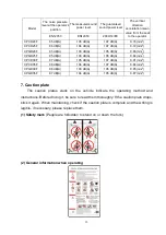
the guaranteed sound power level is referred to the following table. But the noise of the 

forklift  truck  may  fluctuate  due  to  different  operation  and  the  influence  of  the  external 

environment. 

(55) The driver feels the vibration of the forklift truck when operating and traveling the 

forklift truck.. According to ISO3691 and based on EN13059 standard. The vibration of the 

forklift truck fluctuates according to environment condition. In normal working condition, 

the vertical direction acceleration mean value from the seat to the operator by testing is in 

the following table. But the vibration frequency felt by the driver depends on the working 

condition  (etc.  road,  operation  method),  so  the  actual  vibration  frequency  must  be 

determined according to environment condition when necessary. 

(56)  To  prevent  the  fire,  accident  or  other  unpredictable  event,  prepare  the  fire 

extinguishers in advance and operate them according to the instructions. 

Summary of Contents for F Series

Page 1: ...1...

Page 2: ...F Series CPCD20 25 30 35F CPQ Y D20 25 30 35F Internal CombustionCounterbalancedForkliftTruck OPERATION SERVICE MANUAL KION Baoli Jiangsu Forklift Co Ltd 2 3 5T...

Page 3: ...bination meter so they have a lot of advantages such as good performance easy operation wide vision flexible steering reliable braking powerful and aesthetic appearance This manual states the specific...

Page 4: ...truck 13 6 Information of safety operation 15 7 Caution plate 19 Periodic inspection and servicing 24 1 General rules on inspection and maintenance 24 2 Inspection content 25 3 Periodic replacement ta...

Page 5: ...rating device of parking brake 54 4 5 Inspection of wheel brake 55 4 6 Troubleshoot 56 5 Steering system 57 5 1 Hand wheel 58 5 2 Cycloid gear type powered steering unit 58 5 3 Inspection after reasse...

Page 6: ...nance and adjustment 75 8 Electric system 78 8 1 General description 78 8 2 Brief explanation for operation 79 8 3 Instructions of meter panel 80 8 4 Principle diagram of electrical system 85 8 5 Diag...

Page 7: ...1 About F series forklift truck 1 External view and technical parameter Fig1 1 External view...

Page 8: ...12PR 28 9 15 14PR Rear 6 00 9 10PR 6 50 10 10PR Tread Front B2 mm 970 1000 Rear B3 mm 970 Wheelbase Y mm 1650 1700 1760 Ground clearance full load no load Mast M mm 85 105 110 135 Frame F 140 145 170...

Page 9: ...d wide vision for the use of two stage CC extension type mast and hidden type tilt cylinder device The forklift truck can be fitted with 2 stage or 3 stage full free lift mast having different lifting...

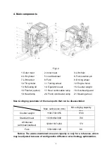
Page 10: ...e mentioned size and capacity is only for a reference which may be adjusted because of configuration difference or technology optimization 1 Outer mast 2 Inner mast 3 Lift chain 4 Lift cylinder 5 Load...

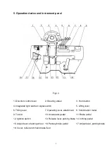
Page 11: ...n signal switch 5 Lifting lever 6 Tilting lever 7 Operating lever attachment 8 Combination meter 9 Tool kit 10 Accelerator pedal 11 Brake pedal 12 Ignition switch 13 Release lever parking brake 14 Inc...

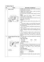
Page 12: ...switch to the START position while the engine is running Do not leave the switch in the ON position when the engine is stopped It may cause over discharge of the battery Do not operate the starter mot...

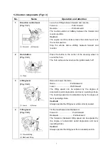
Page 13: ...horn will sound even when the ignition switch off 3 Lifting lever Fig 1 3 5 1 Lower 2 Raise Raise and lower the forks Raise Pull backward Lower Push forward The lifting speed can be adjusted by the de...

Page 14: ...inching pedal Note When control lever is shifted to forward reverse the vehicle will move even the accelerator pedal stays neutral 7 Parking brake pedal Fig 1 3 16 Parking brake release lever Fig 1 3...

Page 15: ...down on the hood until you hear a clicking sound Caution Operating the vehicle without firm locking of the engine hood is very dangerous Be sure to check firm locking before operating the vehicle 3 F...

Page 16: ...ing and driven gear in the reducer after the new forklift truck working for 200 hours 2 Inspection before operation Please pay attention to the following items in order to make the vehicle working wit...

Page 17: ...be morn than 15 seconds Restarting should be after 30 seconds As the engine doesn t work after some times starting should check and remove the trouble do not keep the starting motor engaged for a lon...

Page 18: ...waste cloth and water if needed b While washing the body of the truck check general condition of the truck Especially check the truck s body for recess or damage and tyres for wear and nails or stone...

Page 19: ...n renew oil c Discharge foreign matter and water from the hydraulic reservoir and fuel tank d Remove the cylinder cap check the valves and the rocker shafts for the clearance in normal data e Add cool...

Page 20: ...hould be used The balance weight fork and mast of the truck all have their appointed sling position 4 Towing of forklift truck a The draw bar is installed below the counter weight When operating the d...

Page 21: ...achment should be operated as a loaded truck 10 Connect the power and turn on the key switch select the position of direction switch check the truck for normal operation by turning steering wheel depr...

Page 22: ...handle bulky goods To prevent the collapse of stacked goods tighten them Forbid loading loose or little volume goods without pallet 24 When loading the goods lower the forks to the floor After the for...

Page 23: ...rks of the truck with lifting height more than 3m lift take the protection measures if necessary 39 Before the truck decelerating and stopping don t change gear to reverse shift so as to ensure the sa...

Page 24: ...people the forklift is forbidden operating in airtight space or you may be choked by the tail gas The tail gas s exhausting standard shouldn t be lower than the no load mechanical vehicle exhaust stan...

Page 25: ...84 m s 2 CPCD30F 87 dB A 105 dB A 107 dB A 0 91 m s 2 CPCD35F 86 dB A 104 dB A 107 dB A 0 84 m s 2 CPQD30F 86 dB A 103 dB A 105 dB A 0 85 m s 2 CPQD35F 87 dB A 104 dB A 105 dB A 0 87 m s 2 7 Caution p...

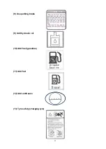
Page 26: ...20 3 Nameplate of forklift truck 4 Lubrication system 5 Capacity chart 6 Inspections before starting 7 Adjust parking brake...

Page 27: ...21 8 Use parking brake 9 Add hydraulic oil 10 Add fuel gasoline 11 Add fuel 12 Add antifreeze 13 Tyre safety charging tyre...

Page 28: ...22 14 Tyre pressure decal charging tyre 2 2 5t forklift truck 3 3 5t forklift truck 15 Sling point indication 16 Sling decal 17 Forbid entering into the space behind the mast...

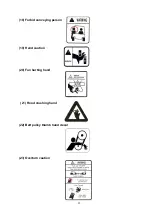
Page 29: ...23 18 Forbid conveying person 19 Hand caution 20 Fan hurting hand 21 Hood crushing hand 22 Belt pulley thumb hand decal 23 Overturn caution...

Page 30: ...lic system 2 Check the reliability of the steering and braking system 3 Check the reliability of mast driving axle and steering axle connecting with the frame 4 Check all wheels for tightness Irregula...

Page 31: ...erred to the corresponding section in the manual or according to the decal of the vehicle 2 After the adjustment check if air is not leaking from the valve Damage crack and wear of tyres and rims Chec...

Page 32: ...om the filler port 3 If the engine coolant is not visible through the filler port fill appropriately diluted coolant LLC to the port Note To close and tighten the radiator cap match the pawl on the re...

Page 33: ...ossible Select the brand number of the engine oil according to the request of the engine or the corresponding section of the manual Leakage inspection Check the engine compartment for any oil or fuel...

Page 34: ...k a professional serviceman for inspection if any abnormality is found Inching and brake pedal inspection 1 Inching and brake pedal 1 Manually depress the inching and brake pedal to check the play unt...

Page 35: ...evers to check their operating state If anything unusual is found have the vehicle inspected by a professional serviceman Steering wheel inspection Perform the inspection after starting the engine 1 C...

Page 36: ...of operation or monthly periods of operation whichever comes sooner Every 6 Weeks 3 6 12 Months Every 250 500 1000 2000 Hours Engine oil Engine oil filter Cooling water except LLC LLC is every 2 years...

Page 37: ...ct and service 7 Steering knuckle king pin Replace 8 Oil tank A MP grease 9 Engine crankcase B Engine oil 10 Pump transmission device C Hypoid gear oil 11 Foot operating assy D Hydraulic oil 12 Direct...

Page 38: ...ng the three catches fixing the element Element cleaning 1 Element 1 Tap the element filter paper lightly without causing any damage or blow dust off with compressed air 7kg cm 2 or less from inside 2...

Page 39: ...nd extract it again to check if the oil level is among the gridding lines on the level gauge Retightening of bolts and nuts Retighten each bolt and nut on the chassis and load handling system Greasing...

Page 40: ...e the radiator and or cylinder block In such cases antifreeze coolant must be used When long life coolant LLC is used it must be changed once every two years Freezing temperature varies depending on t...

Page 41: ...2 Drain plug 3 Drain hose The sedimenter separates the water contained in the fuel It is integrated with the fuel filter If the sedimenter warning lamp comes on immediately drain water according to th...

Page 42: ...n to wash it off with water thoroughly the spot and adjoining area When the battery is dead 1 Dead battery vehicle 2 Engine hanger 3 To frame 4 Booster cable 5 Rescue battery When a booster cable is a...

Page 43: ...3 4 L HV 20 Low temperature antiwear hydraulic fluid L HV32 Rando HDZ 32 Shell tellus oil 32 Univis N32 ISO 6743 4 L HS 40 Low pour point antiwear hydraulic fluid L HS32 Mobil DTE 13M Shell tellus T32...

Page 44: ...2 Engine parameter and appropriate truck model Engine model Rated output Speed Kw r p m Rated torque Speed N m r p m Cylinder number Bore Stroke mm Total displacement L Weight Kg Appropriate truck mod...

Page 45: ...k you must carry out periodic inspection and adjustment of power system 1 Regularly clear the dust of air cleaner 2 Regularly replace oil filter and fuel filter 3 Check and apply the coolant periodica...

Page 46: ...ydraulic drive unit Torque converter Type Three elements single stage two phases Torque ratio 3 Set pressure 0 5 0 68 MPa Charging pump Type Inner mesh gear pump Flow rate 27 L min 2000rpm 1 5MPa Hydr...

Page 47: ...Seal ring 22 Shift arm 39 Single row tapered roller bearing 6 O ring 23 Transmission case cover 40 O ring 7 Charging pump 24 Shift shaft 41 Oil seal 8 Oil seal 25 O ring 42 Single row tapered roller...

Page 48: ...end of which is connected with the axle housing The differential case is bilateral symmetry The differential includes two halfshaft gears and four planet gears The thrust washers are installed between...

Page 49: ...flow angle slows down and the value of the output torque keeps on decreasing until the liquid flows into the leaves of the idler pulley in opposite direction When original reaction torque acts in the...

Page 50: ...rd or backward position the circuit form the slide valve to either the forward clutch or the backward clutch is closed accordingly thus causing corresponding clutch come to work When a clutch is at wo...

Page 51: ...bble in oil Measure and adjust pressure B Slipped clutch 1 Oil pressure lower Measure and adjust pressure 2 Seal ring damaged Check and replace 3 Piston ring of the clutch damaged Check and replace 4...

Page 52: ...of oil pump Check and replace 4 Shaft is broken Check and replace 5 Too low oil pressure Check oil pump for suction pipe Gear box 1 Lower oil amount Check oil level and add oil 2 Seal ring is worn Che...

Page 53: ...ted to the half shaft through the differential and drives the front wheels through the hubs Each hub is fixed on the axle housing with two tapered roller bearings so that the half shafts bear only tor...

Page 54: ...ake the tops of the rim mounting bolts face outside c Don t stand near the tyre when inflating air d When the tyre pressure reaches 98KPa 1kgf cm2 knock the tyre lightly to make the inner tyre and gas...

Page 55: ...49 Fig3 2 Add grease Fig3 3 Measure starting torque Structure of rim bolt Fig3 4 Wheel assembly 1 Tyre 4 Inner rim 7 Spring washer 2 Air valve 5 Outer rim 8 Nut rim 3 Bushing 6 Rim bolt...

Page 56: ...n shim Tighten or replace Blocked air hole Clean or replace Worn or damaged oil seal Replace Noisy differential Worn or damaged gear Replace Worn or damaged bearing Replace Misadjusted gear clearance...

Page 57: ...exterior of the cylinder is protected from dust by means of a rubber dust cover The piston is actuated through the push rod by operation of the brake pedal As the brake pedal is pressed the push rod p...

Page 58: ...harply braked See Fig4 1 Fig4 1 Master cylinder 1 Link rod 6 Piston 2 Push rod 7 Primary cup 3 Dust cover 8 Spring 4 Snap ring 9 Check valve 5 Secondary cup 4 3 Wheel brake The wheel brake is the inte...

Page 59: ...ly when the truck in reverse travel is braked The secondary brake shoe comes into contact with the brake drum and rotates together As a result of this the parking pull rod turns right around the point...

Page 60: ...djuster clockwise the force increases otherwise when you turn the adjuster counterclockwise the force decreases Press force 50kg Operating method Turn off the key press the parking brake pedal with le...

Page 61: ...If necessary replace it 3 Check the operating cylinder spring for free length If necessary replace it 4 Check the friction piece for thickness to see if it is excessively worn If necessary replace it...

Page 62: ...ign matter adhered on it Repair or replace 2 Deformed backing plate or loose bolts Repair or replace 3 Deformed shoe or incorrect installation Repair or replace 4 Worn friction piece Replace 5 Loose w...

Page 63: ...iston type Cylinder bore mm 70 Diameter of piston rod mm 50 Stroke mm 160 Rated pressure Mpa 7 9 10 5 Diameter of handwheel mm 290 Pressure of steering wheel Mpa 0 84 0 76 The steering system principa...

Page 64: ...can be mastered easily through practice 5 2 Cycloid gear type powered steering unit The powered steering unit Fig5 2 can transmit the pressure oil from the flow divider by pipes to the steering cylin...

Page 65: ...y Fail to turn handwheel Oil pump damaged Replace Flow divider blocked or damaged Clean or replace Hose or joint damaged or pipeline blocked Clean or replace Difficult to turn handwheel Too low oil pr...

Page 66: ...kle steering through tie rod causing wheel s deflection and truck s steering The steering axle is bolted to the rear frame by the buffer Fig5 3 Steering axle 1 Axle body 9 Tyre 17 Oil seal 2 Tie rod 1...

Page 67: ...ig5 5 fill up the chamber formed by wheel hubs wheel hub bearing and wheel hub covers with lubricating grease Coat the lips of the oil seals with lubricating grease 2 Press the hub bearing into the hu...

Page 68: ...8N m 7 If the torque value necessary to rotate the hub is more than the specified one above mentioned screw out the castle nut for 1 6 turn and measure the torque value then 8 When the torque value me...

Page 69: ...ed on the right side of the truck 6 2 Hydraulic oil pump Fig6 1 The hydraulic oil pump is a gear pump It is drived directly by the power takeoff device of the engine The oil of the oil tank flows to t...

Page 70: ...64 Fig6 1 Hydraulic pump Fig6 2 Control valve 1 Pump body 2 Driving gear 3 Driven gear 4 Front cover 5 Rear cover 6 Lining plate 7 Seal ring 8 Ring 9 Oil seal 10 Snap ring...

Page 71: ...of the flow divider is quite simple It is of direct overflow type and ensures the constant pressure of the power steering system by balancing the oil pressure with fixed spring force When turning cham...

Page 72: ...crew out the measured hole plug from the inlet port of control valve and install the oil pressure gauge 20MPa on it b Operate the tilt lever measure the pressure when the stroke is to the bottom c Whe...

Page 73: ...piston up When push the lift spool the circuit between the lower part of the lift cylinder and the oil tank is connected and the piston begins to descend due to the weight of the load and all of lifti...

Page 74: ...ng on its outer periphery At the bottom of the lift cylinder there is a cut off valve which operates when the high pressure hose bursts for any reason to prevent the load form dropping from abruptly B...

Page 75: ...oil flows in the reverse position When the oil passes the throttle plate 5 and a pressure difference overcomes the force of the spring 2 and moves the valve core 7 right thus the oil flow being decre...

Page 76: ...s the piston rod The guide sleeve is fitted with dust seal snap ring Yx ring and O ring to prevent oil leakage and keep dust off Fitted with them the guide sleeve is screwed into the cylinder body Whe...

Page 77: ...Disassembly and clean Vibrate and the oil pressure rises slowly Spool is held up Disassembly and clean Exhaust is inadequate Exhaust fully The oil pressure of the steering oil circuit is more than th...

Page 78: ...wn Misadjusted relief valve Adjust pressure to specified value Air entering into the pump Retighten loose connections for suction pipe Add oil into oil tank Replace oil seal Noisy oil pump Worn suctio...

Page 79: ...Lift bracket 2 Inner mast 5 Load backrest 8 Fork 3 Lift cylinder 6 Lift chain 7 1 General description The lifting system is the type of lifting and descending vertically with the two stage rollers It...

Page 80: ...s The main roller shafts are welded on the lift bracket The side rollers fitted on the lift bracket with bolts They roll along the flank plate of the inner mast and rolling clearance can be adjusted w...

Page 81: ...inder as following 1 Install the piston rod in the upper beam of the inner mast without shims 2 Lift the mast slowly to the max stroke of the cylinder and check the two cylinders synchronize or not 3...

Page 82: ...l 7 2 3 Replace rollers of the lift bracket 1 Place a pallet on the forks and let the truck parking on the horizontal ground 2 Make the forks and the pallet down to the ground 3 Disassemble the end ni...

Page 83: ...r the lift cylinder and the bottom of the outer mast Disassemble the lift cylinders and the oil pipes between the two cylinders without loosen the oil pipe joints 6 Main rollers on the upper outer mas...

Page 84: ...be dealed with high precision digital processing The meter consists of a pointing meter drived by two imported step motors and an hour meter with a LCD screen The step motor meter has high reliability...

Page 85: ...se shift the backing lamps light and the back buzzers sound 2 Turning handle switch Pull the turning handle switch to the ON position the front and rear combination lamps clearance tail light Pull the...

Page 86: ...warning lamp is on After 1 2s the lamp is off automatically If this lamp becomes on while the engine is working it means too much water has been accumulated in the water separator After pushing the h...

Page 87: ...type engine 3 Indicator preheating When the ignition switch is turned on the lamp lights and preheating starts The lamp goes out automatically when preheating is over The engine will start easily Cau...

Page 88: ...ut it is necessary to bleed air from the fuel system 8 Timing area After connecting the ignition switch the meter will indicate the working hours It will begin to time after starting the engine The un...

Page 89: ...ature begin from 65 will be displayed in the upper left of LCD 12 Warning lamp water separator Before starting the engine put the key switch to the ON position the meter will do the check automaticall...

Page 90: ...and goes out when the engine starts b If the lamp lights while the engine is running maybe the engine oil is insufficient or the lubrication system is faulty Stop the operation immediately and ask a...

Page 91: ...contact with our company for maintenance 8 4 Principle diagram of electrical system Fig8 2 1 Principle diagram of electrical system 4JG2 Dachai 498 engine Fig8 2 2 Principle diagram of electrical syst...

Page 92: ...Power switch 05 Switch turning lamp 06 Power ignition switch 07 Switch light 08 Switch start 09 Power headlamp 10 Preheating indicating 12 Main power 13 Preheating fuse 14 Starter 15 Optional power 1...

Page 93: ...ower switch 05 Switch turning lamp 06 Power ignition switch 07 Switch light 08 Switch start 09 Power headlamp 10 Preheating indicating 12 Main power 13 Preheating fuse 14 Starter 15 Optional power 1 1...

Page 94: ...04 Power switch 05 Switch turning lamp 06 Power ignition switch 07 Switch light 08 Switch start 09 Power headlamp 10 Preheating indicating 12 Main power 13 Preheating fuse 14 Starter 15 Optional power...

Page 95: ...89 Fig8 3 1 Diagram of harness 4JG2 engine...

Page 96: ...90 Fig8 3 2 Diagram of harness Dachai 498 engine...

Page 97: ...91 Fig8 3 3 Diagram of harness Xinchai 498engine...

Page 98: ...92 Fig8 3 4 Diagram of harness Yanmar 4TNE98 engine...

Page 99: ...93 NOTE...

Page 100: ...94...

Page 101: ...6126 P C 214500 Add No 8 Xinzhou Road Economic Development Zone Jingjiang Jiangsu China www baoli mh com We reserve the right to make any changes or modifications of pictures and specifications in th...

Page 102: ......
Reviews: