Table 10: Sensor Pass/Fail Bits
Bit
Position
15
14
13
12
11
10
9
8
7
6
5
4
3
2
1
0
Vision Tool
15 Pass/
Fail
Vision Tool
14 Pass/
Fail
Vision Tool
13 Pass/
Fail
Vision Tool
12 Pass/
Fail
Vision Tool
11 Pass/
Fail
Vision Tool
10 Pass/
Fail
Vision Tool
9 Pass/Fail
Vision Tool
8 Pass/Fail
Vision Tool
7 Pass/Fail
Vision Tool
6 Pass/Fail
Vision Tool
5 Pass/Fail
Vision Tool
4 Pass/Fail
Vision Tool
3 Pass/Fail
Vision Tool
2 Pass/Fail
Vision Tool
1 Pass/Fail
Camera
Tool Pass/
Fail
13.3.5
Tool-Specific
Results: EtherNet/IP
Configure
the VE to output
user-defined,
tool-specific
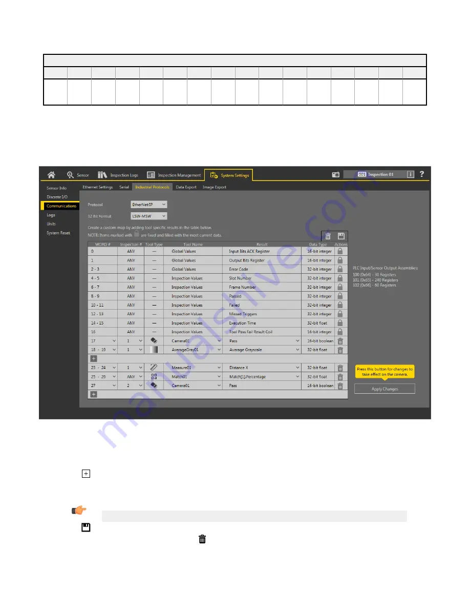
results to the PLC using a custom map.
Each assembly instance includes
system-defined
and
user-defined
results in the map. To set the
user-defined,
tool-specific
results in the
custom map, navigate: System
Settings
>
Communications
> Industrial Protocols.
Figure 296. Industrial Protocols Tab—EtherNet/IP
The results are
configurable
only for the current
inspection.
However, all
user-defined
results in the custom map are shown on the
Industrial Protocols tab whether or not they are included in the current
inspection.
To make changes to a
different
inspection,
switch to
the desired
inspection
and then make changes to the custom map.
Updating
the map does not disconnect the sensor from the PLC.
To
configure
the map:
1. Click
to add a new line to the map.
2. Set the Word/Register/Byte, Tool Name, and Result. See the following
descriptions
for more
information.
3. Click Apply Changes to send the current map to the camera.
Important: Click Apply Changes or all
user-defined
data is lost when you click away from the Industrial Protocols tab.
4. Click
to print and save a PDF of the current map. The PDF includes all data, whether
system-defined
or
user-defined.
5. To return the map to the default
settings,
click . All
user-defined
output data is deleted.
Column
descriptions:
VE Series Smart Camera
www.bannerengineering.com - Tel: 763.544.3164
159


