Quick Start Guide
Self-contained Smart Camera with User-Friendly Vision Manager Software
This guide is designed to help you set up and install the VE Series Smart Camera. For complete information on programming, performance,
troubleshooting, dimensions, and accessories, please refer to the Instruction Manual at
. Search for p/n 191666 to view
the Instruction Manual. Use of this document assumes familiarity with pertinent industry standards and practices. More details are available in the
online help.
WARNING: Not To Be Used for Personnel Protection
Never use this device as a sensing device for personnel protection. Doing so could lead to serious injury or death. This device
does not include the self-checking redundant circuitry necessary to allow its use in personnel safety applications. A sensor
failure or malfunction can cause either an energized or de-energized sensor output condition.
CAUTION: Electrostatic Discharge
Avoid the damage that electrostatic discharge (ESD) can cause to the Sensor.
Always use a proven method for preventing electrostatic discharge when installing a lens or attaching a cable.
CAUTION: Hot Surface
Use caution when handling the camera. The surface of the camera may be hot during operation and immediately after use.
Models
Model1
Resolution
VE200G1A
WVGA, 752 × 480 pixels grayscale
VE201G1A
1.3 MP, 1280 × 1024 pixels grayscale
VE202G1A
2 MP, 1600 × 1200 pixels grayscale
VE205G1A
5 MP, 2592 × 2048 pixels grayscale
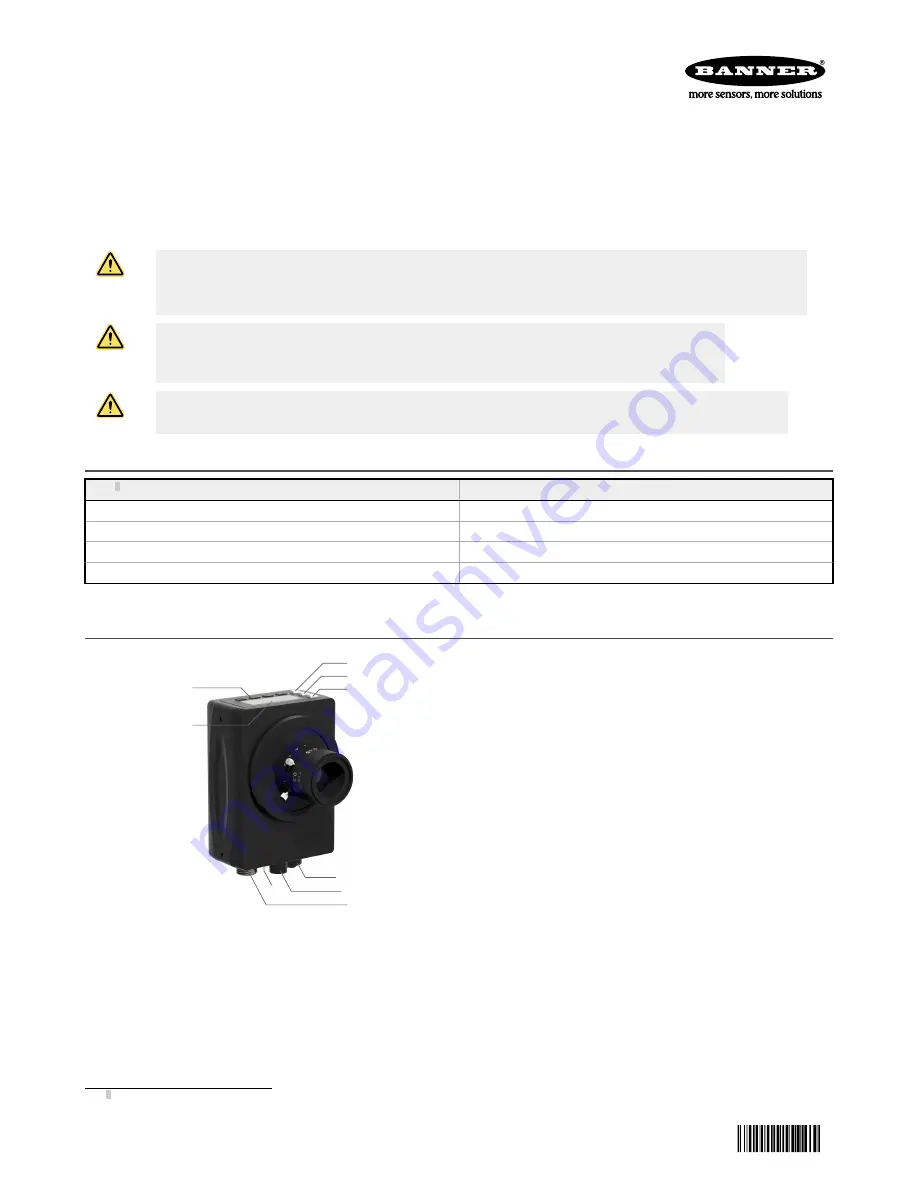
Features
1
2
3
4
5
7
6
8
9
Figure 1. Sensor Features
1. Display
2. Buttons
3. Pass/Fail indicator (green/red)
4. Ready/Trigger indicator (green/amber)
5. Power/Error indicator (green/red)
6. Ethernet indicator (amber), not shown
7. Ethernet connection
8. Light connection
9. Power, Discrete I/O connection
1 Model VE202G2A, 2 MP, 1600 × 1200 grayscale with 4-pin D-code M12 Ethernet connection is also available.
VE Series Smart Camera
Original Document
191667 Rev. G
13 July 2018
191667


