

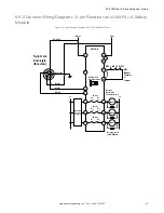
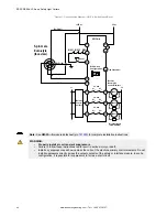
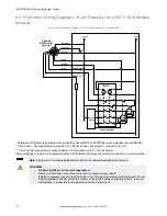


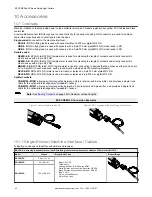
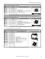
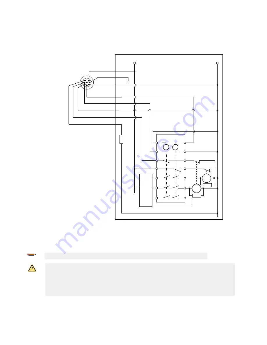
6.5.6 Generic Wiring Diagram—8-pin Receiver and IM-T-9A Interface
Module
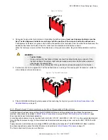
Figure 40. Generic Wiring Diagram—IM-T-9A Interface Module (1-Channel EDM)
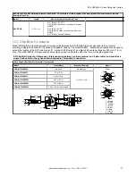
S1
S2
Y1
Y2
Y3
Y4
14
24
34
13
23
33
S4
S3
IM-T-9A
K2
K1
MPCE
2
MPCE
1
Machine
Control
Feedback (optional)
8-pin male
M12/Euro-style
(face view)
Bn (Pin #1)
Gn/Ye (#7)
Bu (#6)
Bk (#5)
Wh (#4)
Vi (#8)
Or (#3)
Or/Bk (#2)
Fault Out ***
*
*
+24 V DC
0 V DC
Scan Code **
* Installation of transient (arc) suppressors across the coils of MPCE1 and MPCE2 is recommended (see WARNING).
** Scan Code 1: Not connected or connected to 0 V DC (as shown). Scan Code 2: connect to 24 V DC.
*** Fault Out: Not connected or connect indicator (70 mA maximum) to 0 V DC (as shown).
Other interfacing modules and solutions available. See the Banner Engineering catalog or website for more information.
Note:
See the IM-T-..A module datasheet (p/n
) for complete installation instructions.
WARNING:
•
Properly install arc or transient suppressors
•
Failure to follow these instructions could result in serious injury or death.
•
Install any suppressors as shown across the coils of the machine primary control elements. Do not
install suppressors directly across the output contacts of the safety or interface module. In such a
configuration, it is possible for suppressors to fail as a short circuit.
EZ-SCREEN
®
LS Basic Safety Light Curtain
52
www.bannerengineering.com - Tel: + 1 888 373 6767