For Sales and Support, Contact Walker EMD • Toll-free: (800) 876-4444 • Tel: (203) 426-7700 • Fax: (203) 426-7800 • www.walkeremd.com
Top Panel Interface
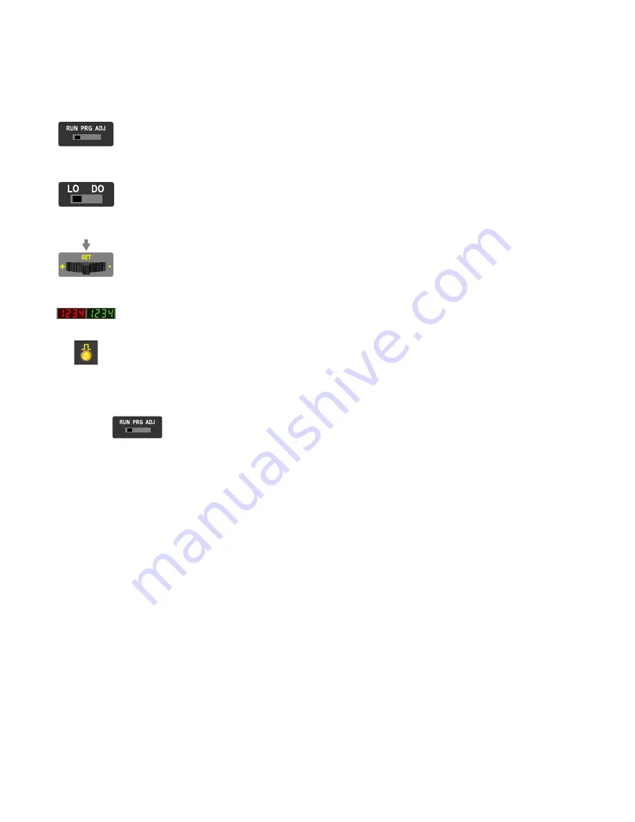
Opening the dust cover provides access to the top panel interface. The top panel interface consists of the RUN/PRG/ADJ mode switch, LO/DO switch, +/SET/- rocker
button, dual red/green digital displays, and output LED.
RUN/PRG/ADJ Mode Switch
The RUN/PRG/ADJ mode switch puts the sensor in RUN, PRG (Program), or ADJ (Adjust) mode. RUN mode allows the sensor to operate normally
and prevents unintentional programming changes via the +/SET/- button. PRG mode allows the sensor to be programmed through the display driven
programming menu (see Program Mode below). ADJ mode allows the user to perform Expert TEACH/SET methods and Manual Adjust (see Adjust
Mode below).
LO/DO Switch
The LO/DO switch is used to select Light Operate or Dark Operate mode. In Light Operate mode, the output is ON when the sensing condition is above
the threshold (for Window SET, the output is ON when the sensing condition is inside the window). In Dark Operate mode, the output is ON when the
sensing condition is below the threshold (for Window SET, the output is ON when the sensing condition is outside the window).
+/SET/- Rocker Button
The +/SET/- rocker button is a 3-way button. The +/- positions are engaged by rocking the button left/right. The SET position is engaged by clicking
down the button while the rocker is in the middle position. All three button positions are used during PRG mode to navigate the display driven program-
ming menu. During ADJ mode, SET is used to perform TEACH/SET methods and +/- are used to manually adjust the threshold(s). The rocker button is
disabled during RUN mode, except when using Window SET, see
Red/Green Digital Displays
During RUN and ADJ mode, the Red display shows the signal level and the Green display shows the threshold. During PRG mode, both displays are
used to navigate the display driven programming menu.
Output LED
The output LED provides a visible indication when the output is activated.
Remote Input
For more information about how to perform TEACH/SET methods and to program the sensor remotely, see the DF-G1 Manual.
Run Mode
Run mode allows the sensor to operate normally and prevents unintentional programming changes. The +/SET/- rocker button is disabled during RUN mode, except when
using Window SET, see
on page 6 .
DF-G1 - Expert Fiber Amplifier Install Sheet
2
www.bannerengineering.com - tel: 763-544-3164
P/N 161275 Rev. A


