Appendix A • Connecting an external device to the mainboard
Appendix A
Automation PC 810 with GM45 CPU board user's manual V1.28
407
2 Connecting an external device to the mainboard
A plug on the mainboard 5 VDC and +12 VDC to be branched off in order to supply special PCI cards,
for example.
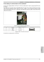
This voltage can be accessed using the "5CAMSC.0001-00" on page 371. The plug is located close to the bus
unit(s) and can be attached to it with a cable tie (see arrow in image). In order to reach the connector, the side
cover (see "Mounting the side cover" on page 397) of the APC810 as well as any slide-in drives and PCI insert
cards must be removed.
Figure 283: Connector location for external devices
Connector for the external devices
Pin
Assignment
Power
1
+12 VDC
2
GND
Max. 10 watts
3
GND
4
+5 VDC
Max. 5 watts
4-pin connector, male
1 2 3 4
Table 299: Pinout - Connector on main board
Connections are protected with a 1A multi-fuse.


