Maintenance / Service • Installing the UPS module
Chapter 7
Maintenance / Service
Automation PC 810 with GM45 CPU board user's manual V1.28
383
7 Installing the UPS module
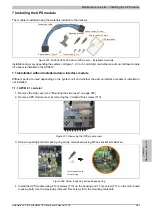
The module is installed using the materials included in the delivery.
Connection cable
Mounting bracket
Spacer bolts (14 mm)
Spacer bolts (16 mm)
Torx screws (T10)
Spacer sleeve (2 mm)
UPS insulation
Figure 230: 5AC600.UPSI-00 Add-on UPS module – Installation materials
Installation may vary depending the system unit type (1, 2, 3 or 5 card slots) or whether an add-on interface module
(IF option) is installed in the APC810.
7.1 Installation without installed add-on interface module
Different parts are used depending on the system unit and whether the add-on interface module is installed or
not installed.
7.1.1 APC810 1 card slot
1. Remove the side cover (see "Mounting the side cover" on page 397).
2. Remove UPS module cover by removing the 2 marked Torx screws (T10).
Figure 231: Removing the UPS module cover
3. Screw in spacing bolt and spacing ring on the main board (using M5 hex socket screwdriver).
14 mm spacer bolts
+ Spacer ring
Figure 232: Screw in spacing bolt and spacing ring
4. Install the UPS module using 2 Torx screws (T10) on the housing and 1 Torx screw (T10) on the main board
(spacing bolt). Use the previously removed Torx screws from the mounting materials.


